You may substitute:
3.5Ω 1000W load resistor (6030A)
0.069Ω 1000W load resistor (6031A)
0.4Ω 1000W load resistor (6032A)
40Ω 1000W load resistor (6035A) in these tests:
CV Load Effect (Load Regulation) CV PARD (Ripple and Noise)
CCSource Effect (Line Regulation) CC PARD (Ripple and Noise)
The substitution of the load resistor requires adding a load switch and making minor changes to the procedures. The load transient recovery time test procedure is not amenable to modification for use with load resistors.
An electronic load is considerably easier to use than a load resistor. It eliminates the need for connecting resistors or rheostats in parallel to handle the power, it is much more stable than a
Note: A
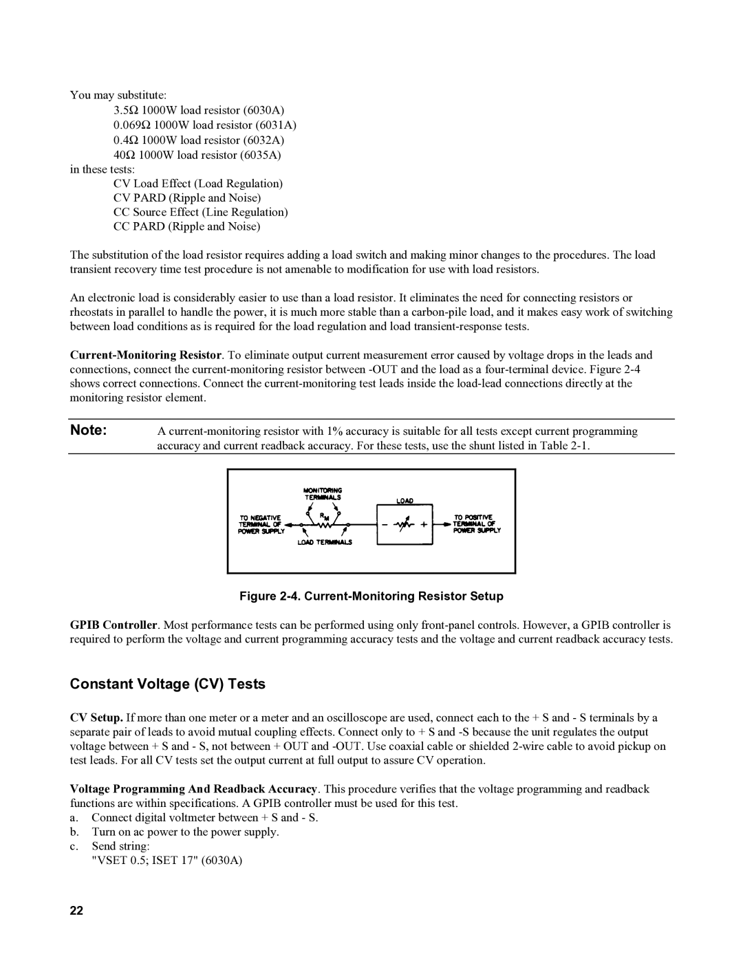
Figure 2-4. Current-Monitoring Resistor Setup
GPIB Controller. Most performance tests can be performed using only
Constant Voltage (CV) Tests
CV Setup. If more than one meter or a meter and an oscilloscope are used, connect each to the + S and - S terminals by a separate pair of leads to avoid mutual coupling effects. Connect only to + S and
Voltage Programming And Readback Accuracy. This procedure verifies that the voltage programming and readback functions are within specifications. A GPIB controller must be used for this test.
a.Connect digital voltmeter between + S and - S.
b.Turn on ac power to the power supply.
c.Send string:
"VSET 0.5; ISET 17" (6030A)
22