The A4 FET Board should only be raised on an extender when using the main troubleshooting setup. NEVER use a FET Board extender when the unit is operated with its normal ( ≈ 320Vdc) bus voltage. To do so is a personal shock hazard and can damage the power supply.
To troubleshoot the power supply the A4 power FET board and A2 control board can be raised out of the unit using extender boards and cables provided in service kit P/N
Main Troubleshooting Setup
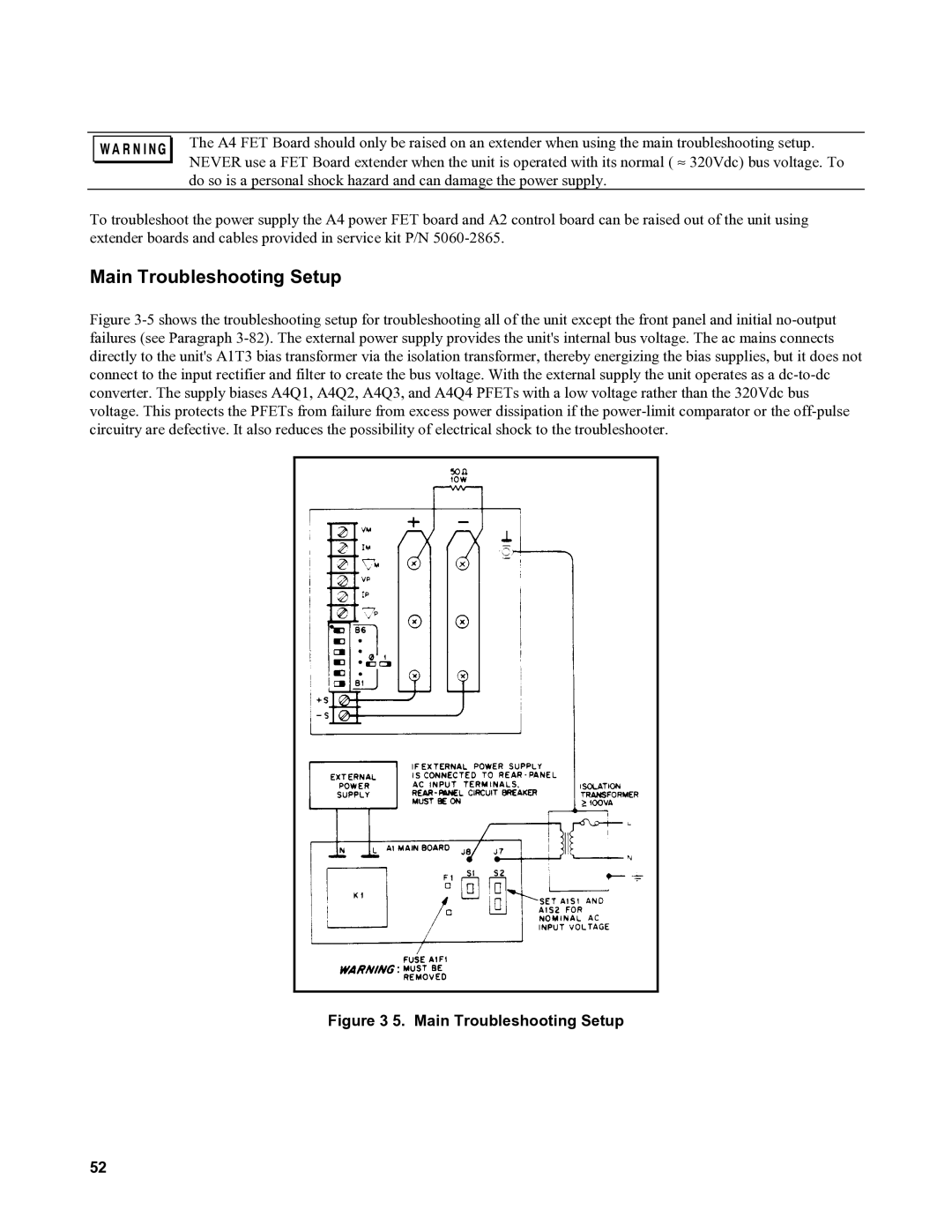
Figure 3-5 shows the troubleshooting setup for troubleshooting all of the unit except the front panel and initial no-output failures (see Paragraph 3-82). The external power supply provides the unit's internal bus voltage. The ac mains connects directly to the unit's A1T3 bias transformer via the isolation transformer, thereby energizing the bias supplies, but it does not connect to the input rectifier and filter to create the bus voltage. With the external supply the unit operates as a dc-to-dc converter. The supply biases A4Q1, A4Q2, A4Q3, and A4Q4 PFETs with a low voltage rather than the 320Vdc bus voltage. This protects the PFETs from failure from excess power dissipation if the power-limit comparator or the off-pulse circuitry are defective. It also reduces the possibility of electrical shock to the troubleshooter.
Figure 3 5. Main Troubleshooting Setup
52