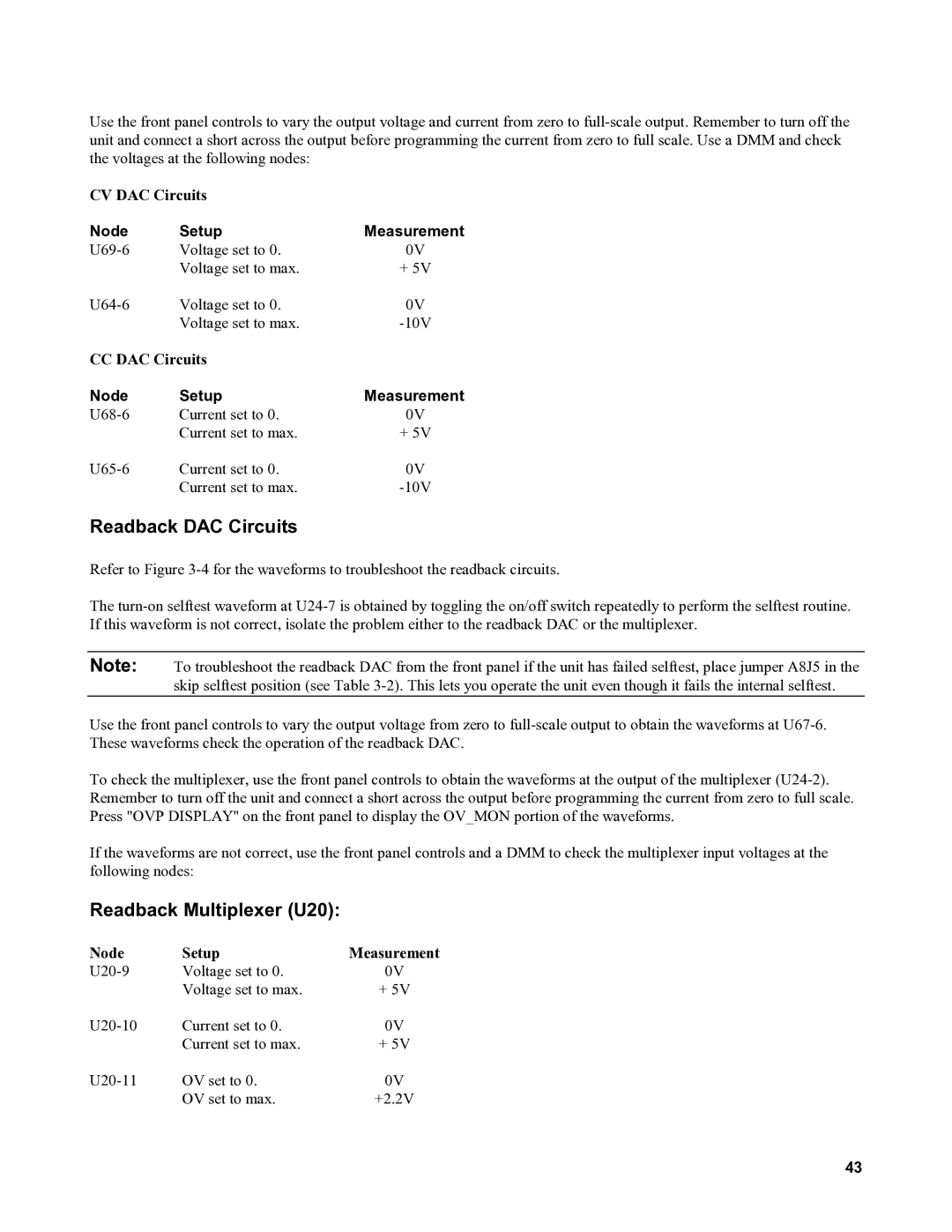
Use the front panel controls to vary the output voltage and current from zero to
CV DAC Circuits
Node | Setup | Measurement |
Voltage set to 0. | 0V | |
| Voltage set to max. | + 5V |
Voltage set to 0. | 0V | |
| Voltage set to max. | |
CC DAC Circuits |
| |
Node | Setup | Measurement |
Current set to 0. | 0V | |
| Current set to max. | + 5V |
Current set to 0. | 0V | |
| Current set to max. | |
Readback DAC Circuits
Refer to Figure
The
Note: To troubleshoot the readback DAC from the front panel if the unit has failed selftest, place jumper A8J5 in the skip selftest position (see Table
Use the front panel controls to vary the output voltage from zero to
To check the multiplexer, use the front panel controls to obtain the waveforms at the output of the multiplexer
If the waveforms are not correct, use the front panel controls and a DMM to check the multiplexer input voltages at the following nodes:
Readback Multiplexer (U20):
Node | Setup | Measurement |
Voltage set to 0. | 0V | |
| Voltage set to max. | + 5V |
Current set to 0. | 0V | |
| Current set to max. | + 5V |
OV set to 0. | 0V | |
| OV set to max. | +2.2V |
43
