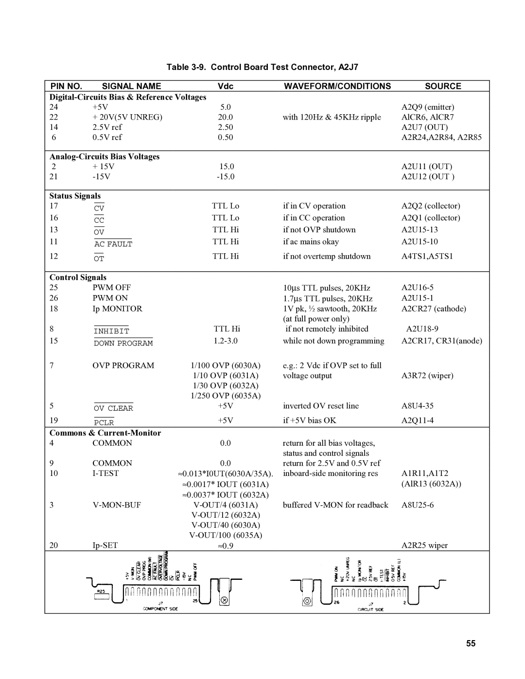
Table 3-9. Control Board Test Connector, A2J7
PIN NO. |
|
| SIGNAL NAME | Vdc | WAVEFORM/CONDITIONS | SOURCE | |||||||
|
|
| |||||||||||
24 | +5V | 5.0 |
| A2Q9 (emitter) | |||||||||
22 | + 20V(5V UNREG) | 20.0 | with 120Hz & 45KHz ripple | AlCR6, AlCR7 | |||||||||
14 | 2.5V ref | 2.50 |
| A2U7 (OUT) | |||||||||
6 | 0.5V ref | 0.50 |
| A2R24,A2R84, A2R85 | |||||||||
|
|
|
|
|
|
|
|
|
|
|
|
| |
|
|
| |||||||||||
2 | + 15V | 15.0 |
| A2U11 (OUT) | |||||||||
21 |
| A2U12 (OUT ) | |||||||||||
|
|
|
|
|
|
|
|
|
|
|
|
| |
Status Signals |
|
|
| ||||||||||
17 |
|
|
|
|
|
|
|
|
|
| TTL Lo | if in CV operation | A2Q2 (collector) |
| CV | ||||||||||||
16 |
|
|
|
|
|
|
|
|
| TTL Lo | if in CC operation | A2Q1 (collector) | |
| CC | ||||||||||||
13 |
|
|
|
|
|
|
|
|
| TTL Hi | if not OVP shutdown | ||
| OV | ||||||||||||
11 |
|
|
|
|
|
|
|
| TTL Hi | if ac mains okay | |||
| AC FAULT | ||||||||||||
12 |
|
|
|
|
|
|
|
| TTL Hi | if not overtemp shutdown | A4TS1,A5TS1 | ||
| OT | ||||||||||||
|
|
|
|
|
|
|
|
| |||||
Control Signals |
|
|
| ||||||||||
25 | PWM OFF |
| 10∝s TTL pulses, 20KHz | ||||||||||
26 | PWM ON |
| 1.7∝s TTL pulses, 20KHz | ||||||||||
18 | Ip MONITOR |
| 1V pk, ½ sawtooth, 20KHz | A2CR27 (cathode) | |||||||||
|
|
|
|
|
|
|
|
|
|
|
| (at full power only) |
|
8 |
|
|
|
|
|
| TTL Hi | if not remotely inhibited | |||||
INHIBIT | |||||||||||||
15 |
|
|
|
|
| while not down programming | A2CR17, CR31(anode) | ||||||
| DOWN PROGRAM | ||||||||||||
7 | OVP PROGRAM | 1/100 OVP (6030A) | e.g.: 2 Vdc if OVP set to full |
| |||||||||
|
|
|
|
|
|
|
|
|
|
| 1/10 OVP (6031A) | voltage output | A3R72 (wiper) |
|
|
|
|
|
|
|
|
|
|
| 1/30 OVP (6032A) |
|
|
|
|
|
|
|
|
|
|
|
|
| 1/250 OVP (6035A) |
|
|
5 |
|
|
|
|
| +5V | inverted OV reset line | ||||||
| OV CLEAR | ||||||||||||
19 |
|
|
| +5V | if +5V bias OK | ||||||||
PCLR | |||||||||||||
Commons & |
|
|
| ||||||||||
4 | COMMON | 0.0 | return for all bias voltages, |
| |||||||||
|
|
|
|
|
|
|
|
|
|
|
| status and control signals |
|
9 | COMMON | 0.0 | return for 2.5V and 0.5V ref |
| |||||||||
10 |
| ≈0.013*I0UT(6030A/35A). | A1R11,A1T2 | ||||||||||
|
|
|
|
|
|
|
|
|
|
| ≈0.0017* IOUT (6031A) |
| (AlR13 (6032A)) |
|
|
|
|
|
|
|
|
|
|
| ≈0.0037* IOUT (6032A) |
|
|
3 |
| buffered | |||||||||||
|
|
|
|
|
|
|
|
|
|
|
|
| |
|
|
|
|
|
|
|
|
|
|
|
|
| |
20 |
| A2R25 wiper | |||||||||||
≈0.9 |
| ||||||||||||
|
|
|
|
|
|
|
|
|
|
|
|
|
|
55