Agilent Technologies
Warn in G
WA R N I N G
Agilent Technologies Sales and Service Offices
Japan 0120 421 0120 421 678 FAX Mexico 5081
Conventions used in this Manual
Structure of this Manual
This manual is divided into 5 parts
Related Manuals
T E
Table of Contents
Specific Command Summary
Root Layer Command
Signal Generation The SOURce Subsystem
Signal Conditioning
Installing the Agilent 816x Instrument Driver
Using Visual Programming Environments
Features of the Agilent 816x Instrument Driver
Error Handling
Compatibility Issues
Preset Defaults
Removed Command
Obsolete Commands
Operational/Questionable Status System for
Agilent 8163A/B, 8164A/B & 8166A/B Mainframes, Sixth Edition
Agilent 8163A/B, 8164A/B & 8166A/B Mainframes, Sixth Edition
List of Tables
Agilent 8163A/B, 8164A/B & 8166A/B Mainframes, Sixth Edition
Introduction to Programming
Gpib Interface
Camino del Rio South, Suite 340 San Diego, CA
Introduction to Programming
Scpi Consortium Office Bode Enterprise
Mnemonic Function
Returning the Instrument to Local Control
If the instrument is in remote control, a screen resembling
Gpib Interface
Message Queues
Message Queues
How the Input Queue Works
Clearing the Input Queue
Output Queue
Error Queue
If no error has occurred, the error queue contains
If more than 29 errors are put into the queue, the message
Is placed as the last message in the queue
Programming and Syntax Diagram Conventions
Command message is ended by a line feed character LF or
Crlf
Statusoperationenable
Short Form and Long Form
Is in long form Short form of this message is
Statoperenab
Command and Query Syntax
Unit Default Allowed Mnemonics
Units
String Value Wsp
Data Types
Slot and Channel Numbers
Laser Selection Numbers
Input to your Return Loss module for the following commands
112,
Common Commands
Common Commands
Gives a summary of the common commands
Common Command Summary
Parameter Function
All bits shown as are unused Event Status Enable Mask
ESE sets the Standard Event Status Enable Mask
Common Status Information
T E
Status Model
Status Registers
Status Model
Slot Status Event
Status System for 8163A/B & 8164A/B
Slot Status Condition
Status System for 8166A/B
Annotations
Status Byte Register
Standard Event Status Register
Operation/Questionable Status Summary
Operation/Questionable Status Summary Register
Operation/Questionable Slot Status
Operation Slot Status Register
Questionable Slot Status Register
Status Model
Status Command Summary
Long
Other Commands
OPT? WAI IDN?
Introduction to Programming
Specific Commands
Specific Command Summary
Specific Commands
Command Description
WAVelengthREFerence/?
Command Description DISPlay
FETChnCHANnelmSCALar
INITiatenCHANnelm
INPUTnCHANnelm
PATH/?
Terminals
READnCHANnelm
ROUTen
SENSenCHANnelmPOWer
SENSenCHANnelmFUNCtion
Command Description SENSenCHANnelmPOWerReference
SENSenCHANnelmRETurnlossCALibration
SENSenCHANnelmRETurnlossCORRection
SLOTn
SOURcenCHANnelmPOWer
SOURcenCHANnelmPOWerATTenuationl
SOURcenCHANnelm
SOURcenCHANnelmAM
SOURcenCHANnelmWAVelengthCORRection
SOURcenCHANnelmWAVelengthREFerence
Command Description SOURcenCHANnelmWAVelengthSWEep
SOURcenCHANnelmWAVelengthSWEepSTEP
Command Description SPECial
STATusn
STATusOPERation
STATusnOPERation
Command Description STATusnQUEStionable
Slot n
SYSTem
SYSTemCOMMunicateGPIB
Specific Commands
Instrument Setup and Status
IEEE-Common Commands
Instrument Setup and Status
Error queue
At power-on By sending a value of zero
Standard event status register Sesr
Status byte register STB
ESE?
Bit Mnemonic Decimal Value
Complete, Command Idle State
Power-on
Parameters None Response Identification terminated by END
Agilent Technologies Manufacturer
Plete, Command Idle State
Lead to useful gains in program execution efficiency
Slot 1 for the Agilent 8163A/B and Agilent 8166A/B
Example OPT? → 81682A , , 81533B, 81532A, END
Error queue
Following are not changed
Bits Mnemonic
Selftest failed on Mainframe
WAI
Pending operations, are completed during the wait period
Status Reporting The STATus Subsystem
STATusOPERationEVENtLEVel0?
Bits Mnemonics
Agilent 8163A/B Agilent 8164A/B Agilent 8166A/B
Status Reporting The STATus Subsystem
STATusOPERationCONDitionLEVel0?
STATusOPERationENABleLEVel
STATusOPERationENABleLEVel0?
STATusOPERationEVENtLEVel1?
Bits Mnemonics Decimal Value Agilent 8166A/B
STATusOPERationENABleLEVel1
Syntax STATusOPERationENABleLEVel1wspvalue Description
STATusOPERationENABleLEVel1?
STATusOPERationCONDitionLEVel1?
Offset
Extrapolated values
STATus nOPERationEVENt?
STATus nOPERationCONDition?
STATusnOPERationENABle
STATusnOPERationENABlewspvalue
STATusnOPERationENABle?
STATusPRESet
Agilent 8163A/B Agilent 8164A/B
STATusQUEStionableEVENtLEVel0?
Statques? → +0END
STATusQUEStionableCONDitionLEVel0?
STATusQUEStionableENABleLEVel0?
STATusQUEStionableENABleLEVel
STATusQUEStionableEVENtLEVel1?
Syntax STATusQUEStionableENABleLEVel 1wspvalue Description
STATusQUEStionableENABleLEVel1?
STATusQUEStionableCONDitionLEVel 1?
Syntax STATusQUEStionableCONDitionLEVel 1? Description
STATusnQUEStionableEVENt?
Syntax STATusnQUEStionableEVENt? Description
11-15 Not Used
STATusnQUEStionableCONDition?
STATusnQUEStionableENABlewspvalue
STATusnQUEStionableENABle
STATusnQUEStionableENABle?
SYSTemDATE
SYSTemERRor?
SYSTemDATE?
Output and error queues
Standard Event Status Enable Mask SESEM,
Gpib interface state
Backlight and contrast of the display
SYSTemTIME?
SYSTemVERSion?
SYSTemCOMMunicateGPIBSELFADDRess
Systcommgpibaddr
Measurement Operations & Settings
Measurement Operations & Settings
Root Layer Command
LOCK?
Agilent Technologies as the manufacturer
Manufacturer
Slot nEMPTy?
Slot nIDN?
SLOTnHEADnEMPTy?
SLOTnTST?
SLOTnHEADnIDN?
SLOTnHEADmOPTions?
SLOTnHEADmTST?
SLOTnHEADmWAVelengthRESPonse?
Syntax SLOTnHEADmWAVelengthRESPonse? Description
SLOTnHEADmWAVelengthRESPonseCSV?
SPECialREBoot
SLOTnHEADmWAVelengthRESPonseSIZE?
Command
Measurement Functions SENSe Subsystem
Agilent 81635A and Agilent 81619A Master Slave Channels
Measurement Functions The SENSe Subsystem
SENSenCHANnelmPOWerUNIT/? SENSenCHANnelmPOWerWAVelength/?
FETChnCHANnelmSCAlarPOWerDC?
FETChnCHANnelmSCAlarRETurnloss?
INITiatenCHANnelmIMMediate
FETChnCHANnelmSCAlarMONitor?
INITiatenCHANnelmCONTinuous
Read nCHANnel mSCALarPOWerALL?
INITiate nCHANnel mCONTinuous?
Read nCHANnel mPOWerALLCONFig?
READnCHANnelmSCALarPOWerDC?
Ber
Member of the pair represents the channel number
READnCHANnelmSCALarMONitor?
READnCHANnelmSCALarRETurnloss?
SENSenCHANnelmCORRectionLOSSINPutMAGNitude?
SENSe nCHANnel mCORRectionLOSSINPutMAGNitude
SENSenCHANnelmCORRectionCOLLectZERO
Operation
SENSe nCHANnel mCORRectionCOLLectZERO?
SENSenCHANnelmCORRectionCOLLectZEROALL
Averaging Time
SENSenCHANnelmFUNCtionPARameterLOGGing
SENSenCHANnelmFUNCtionPARameterLOGGing?
SENSenCHANnelmFUNCtionPARameterMINMax
SENSenCHANnelmFUNCtionPARameterMINMax?
Cont
Wind
SENSenCHANnelmFUNCtionPARameterSTABility
Period time
Averaging Time Period Time
Response Example Affects Dual sensors
SENSenCHANnelmFUNCtionPARameterSTABility?
SENSenCHANnelmFUNCtionRESult?
Sens1funcres? →
Return Loss modules
SENSe nCHANnel mFUNCtionRESultBLOCk?
SENSe nCHANnel mFUNCtionRESultMAXBlocksize?
SENSenCHANnelmFUNCtionRESultMONitor?
SENSenCHANnelmFUNCtionSTATe
100
SENSenCHANnelmFUNCtionSTATe?
SENSenCHANnelmPOWerATIMe
101
SENSenCHANnelmFUNCtionTHReshold
SENSenCHANnelmFUNCtionTHReshold?
SENSenCHANnelmPOWerATIMe?
SENSenCHANnelmPOWerRANGeUPPer
Range Upper Linear Power Limit
102
SENSenCHANnelmPOWerRANGeUPPer?
SENSenCHANnelmPOWerRANGeMONitorUPPer
103
Range Upper Linear
SENSenCHANnelmPOWerRANGeMONitorUPPer?
SENSenCHANnelmPOWerRANGeAUTO
Ment. Otherwise, it must be set by the sensnpowrang command
SENSenCHANnelmPOWerRANGeAUTO?
Reference mode using the command
105
You must append a unit type
DB if you use TOMODule or
SENSenCHANnelmPOWerREFerenceDISPlay
SENSenCHANnelmPOWerREFerenceSTATe
SENSenCHANnelmPOWerREFerenceSTATe?
106
SENSe nCHANnel mPOWerREFerenceSTATeRATio
SENSenCHANnelmPOWerREFerenceSTATeRATio?
107
To the channel for the second value
SENSe nCHANnel mPOWerUNIT
SENSenCHANnelmPOWerUNIT?
SENSenCHANnelmPOWerWAVelength
108
SENSenCHANnelmPOWerWAVelength?
109
SENSenCHANnelmRETurnlossCALibrationFACTory
SENSenCHANnelmRETurnlossCALibrationFACTory
110
SENSe nCHANnel mRETurnlossCALibrationCOLLectTERMination
Defined termination reference measurement. See
SENSe nCHANnel mRETurnlossCALibrationTERMination?
SENSenCHANnelmRETurnlossCORRectionFPDeltal
111
SENSenCHANnelmRETurnlossCORRectionFPDeltal?
112
SENSe nCHANnel mRETurnlossCORRectionREFLectance l
DB reference
Lower wavelength source is denoted by
Signal Generation The SOURce Subsystem
113
OUTPutnCHANnelmCONNection
OUTPutnCHANnelmCONNection?
OUTPutnCHANnelmPATH?
114
OUTPutnCHANnelmSTATe
SOURcenCHANnelmAMINTernalFREQuencyl
115
SOURcenCHANnelmAMINTernalFREQuencyl?
116
SOURcenCHANnelmAMSOURcel
Syntax SOURcenCHANnelmAMSOURcelwsp
INTINT1INT2COHCAEXTEXTDEXTWVLLBACK012356
117
SOURcenCHANnelmAMSTATel
SOURcenCHANnelmAMSTATel?
Wavelength source is denoted by
118
SOURce nCHANnel mAMCOHCtrlCOHLevel l
SOURcenCHANnelmAMCOHCtrlCOHLevell?
SOURcenCHANnelmFMSOURcel
119
SOURce nCHANnel mFMSOURce l?
SOURcenCHANnelmFMSTATel
SOURcenCHANnelmFMSTATel?
120
SOURcenCHANnelmFMSBSCtrlFREQuencyl
Mhzkhzhzminmaxdef
SOURcenCHANnelmFMSBSCtrlFREQuencyl?
121
SOURcenCHANnelmFMSBSCtrlLevell?
SOURcenCHANnelmMODout
SOURcenCHANnelmMODout?
SOURcenCHANnelmPOWerATTenuationl?
122
SOURcenCHANnelmPOWerATTenuationlAUTO
SOURcenCHANnelmPOWerATTenuationlAUTO?
SOURcenCHANnelmPOWerATTenuationlDARK
This command is available in Attenuation Mode Only
SOURcenCHANnelmPOWerLEVelIMMediateAMPLitudel
SOURcenCHANnelmPOWerATTenuationlDARK?
124
125
SOURcenCHANnelmPOWerLEVelIMMediateAMPLitudel?
Also allowed MIN minimum amplitude level
SOURcenCHANnelmPOWerLEVelRISetimel?
SOURcenCHANnelmPOWerLEVelRISetimel
126
SOURce nCHANnel mPOWerSTATe
SOURcenCHANnelmPOWerSTATe?
SOURcenCHANnelmPOWerUNIT
SOURcenCHANnelmPOWerUNIT?
SOURcenCHANnelmPOWerWAVelength?
SOURcenCHANnelmPOWerWAVelength
128
129
SOURce nCHANnel mREADoutDATA?
Pmax
SOURce nCHANnel mREADoutDATABLOCk?
130
SOURcenCHANnelmWAVelengthCWlFIXEDlwspvalue
SOURcenCHANnelmREADoutPOINts?
SOURcenCHANnelmWAVelengthCWlFIXEDl
SOURcenCHANnelmWAVelengthCWlFIXEDl?
131
SOURcenCHANnelmWAVelengthCORRectionARA
132
SOURce nCHANnel mWAVelengthCORRectionARAALL
SOURce nCHANnel mWAVelengthCORRectionAUTocalib
81989A, 81949A
SOURce nCHANnel mWAVelengthCORRectionZERO
133
SOURcenCHANnelmWAVelengthCORRectionZEROALL
134
SOURcenCHANnelmWAVelengthCORRectionZEROAUTO
SOURcenCHANnelmWAVelengthFREQuencyl
Thzghzmhzkhzhz
135
SOURcenCHANnelmWAVelengthFREQuencyl?
SOURcenCHANnelmWAVelengthREFerencel?
SOURcenCHANnelmWAVelengthREFerenceDISPlay
SOURcenCHANnelmWAVelengthSWEepCHECkparams?
136
Message
137
ValueMINMAXDEF0
SOURce nCHANnel mWAVelengthSWEepCYCLes
SOURce nCHANnel mWAVelengthSWEepCYCLes?
138
SOURce nCHANnel mWAVelengthSWEepDWELl
SOURce nCHANnel mWAVelengthSWEepDWELl?
SOURcenCHANnelmWAVelengthSWEepEXPectedtriggers?
139
SOURcenCHANnelmWAVelengthSWEepFLAG?
Sweep state
Start Sweep waiting for trigger Trigger →
Following settings are the prerequisites for Lambda Logging
140
SOURcenCHANnelmWAVelengthSWEepLLOGging
SOURcenCHANnelmWAVelengthSWEepLLOGgingwspOFFON01
141
SOURcenCHANnelmWAVelengthSWEepMODE
SOURcenCHANnelmWAVelengthSWEepMODE?
SOURcenCHANnelmWAVelengthSWEepPMAX?
SOURcenCHANnelmWAVelengthSWEepREPeat
142
SOURcenCHANnelmWAVelengthSWEepREPeat?
143
SOURce nCHANnel mWAVelengthSWEepSOFTtrigger
SOURcenCHANnelmWAVelengthSWEepSPEed
SOURcenCHANnelmWAVelengthSWEepSPEed?
144
SOURce nCHANnel mWAVelengthSWEepSTARt
SOURcenCHANnelmWAVelengthSWEepSTARt?
SOURcenCHANnelmWAVelengthSWEepSTOP
If you enable lambda logging see
145
SOURcenCHANnelmWAVelengthSWEepSTOP?
SOURcenCHANnelmWAVelengthSWEepSTATe
146
SOURcenCHANnelmWAVelengthSWEepSTATe?
SOURcenCHANnelmWAVelengthSWEepSTEPNEXT
SOURcenCHANnelmWAVelengthSWEepSTEPPREVious
147
SOURce nCHANnel mWAVelengthSWEepSTEPWIDTh?
Signal Conditioning
INPut and OUTput commands
148
INPut nCHANnel mATTenuation
149
INPutnCHANnelmOFFSet
INPutnCHANnelmOFFSet?
INPutnCHANnelmOFFSetDISPlay
INPutnCHANnelmOFFSetPOWermeter
150
INPutnCHANnelmATTenuationSPEed
INPutnCHANnelmATTenuationSPEed?
151
INPutnCHANnelmWAVelength
MAX DEF
INPutnCHANnelmWAVelength?
OUTPutnCHANnelmPOWer
OUTPutnCHANnelmPOWer?
152
OUTPut nCHANnel mAPMode?
OUTPutnCHANnelmPOWerREFerence
OUTPutnCHANnelmPOWerREFerence?
OUTPutnCHANnelmPOWerREFerencePOWermeter
153
OUTPutnCHANnelmPOWerOFFSet
OUTPutnCHANnelmPOWerOFFSet?
OUTPutnCHANnelmPOWerOFFSetPOWermeter
154
OUTPut nCHANnel mPOWerCONTRol
OUTPutnCHANnelmPOWerCONTRol?
OUTPutnCHANnelmPOWerUNit
155
OUTPut nCHANnel mPOWerUNit?
OUTPutnCHANnelmSTATeAPOWeron
156
OUTPut nCHANnel mSTATe
OUTPutnCHANnelmSTATeAPOWeron?
157
OUTPutnCHANnelmATIMe
OUTPutnCHANnelmATIMe?
OUTPutnCHANnelmCORRectionCOLLectionZEROALL
158
OUTPCORRCOLLZER0? → 0END
Table of wavelength-dependent offsets
159
CONFigurenCHANnelmOFFSetWAVelengthSTATe
CONFigurenCHANnelmOFFSetWAVelengthSTATe?
160
CONF1OFFSWAVSTAT on
CONFigurenCHANnelmOFFSetWAVelengthVALue
CONFigurenCHANnelmOFFSetWAVelengthREFerence
161
CONF1OFFSWAVREF 4,2
CONFigurenCHANnelmOFFSetWAVelengthREFerence?
CONFigurenCHANnelmOFFSetWAVelengthVALueWAVelength?
CONFigurenCHANnelmOFFSetWAVelengthVALueOFFSet?
162
CONFigurenCHANnelmOFFSetWAVelengthVALuePAIR?
CONFigurenCHANnelmOFFSetWAVelengthVALueDELete
CONFigurenCHANnelmOFFSetWAVelengthVALueDELeteALL
163
CONFigurenCHANnelmOFFSetWAVelengthTABle?
CONFigurenCHANnelmOFFSetWAVelengthTABleSIZE?
164
CONF1OFFSWAVTABSIZE? →
When the attenuator is hosted in Slot
TIP Query the Scpi error queue using SYSTERR?
Slot Numbers
165
Command Semantic
166
Ieee Commands
Display and System Commands
167
User Calibration Data
Status Commands
168
Signal Routing
Switch modules
169
ROUTe nCHANnel m
ROUTenCHANnelmCONFig?
Syntax ROUTenCHANnelmCONFig? Description
ROUTenCHANnelmCONFigROUTe?
170
Triggering The TRIGger Subsystem
171
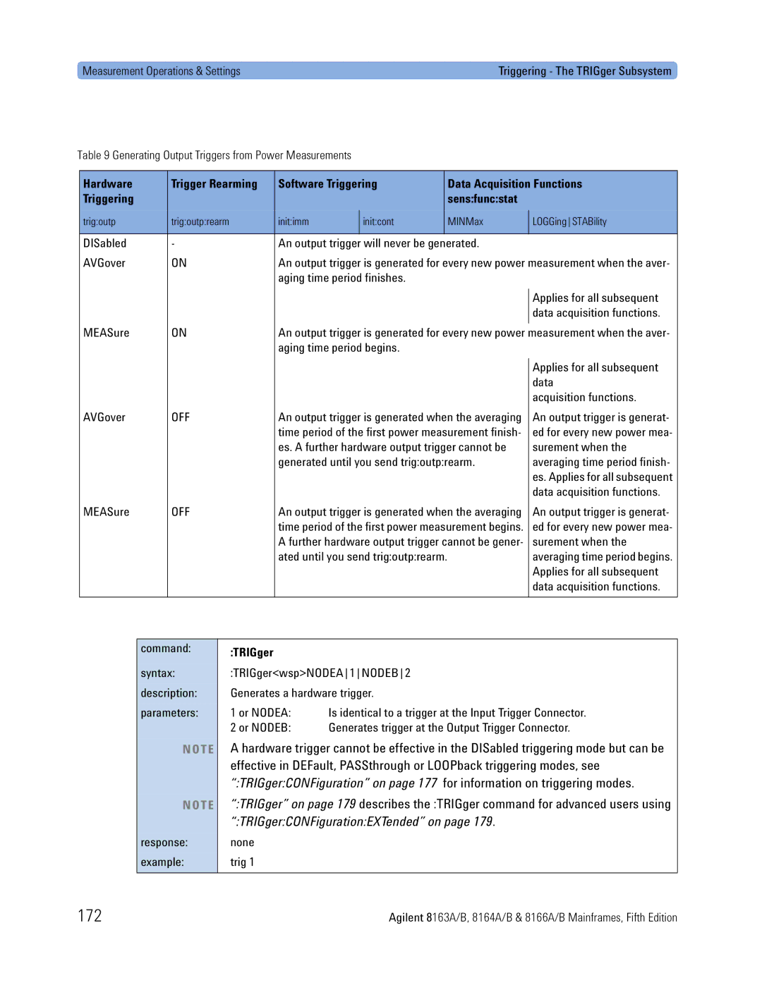
Hardware
Software Triggering Data Acquisition Functions Sensfuncstat
Generating Output Triggers from Power Measurements
DISabled An output trigger will never be generated AVGover
172
Software Triggering Data Acquisition Functions
173
TRIGgernCHANnelmINPut?
174
TRIGgernCHANnelmINPutREARm
175
TRIGger nCHANnel mINPutREARm?
TRIGgernCHANnelmOFFSet
TRIGgernCHANnelmOFFSet value
176
TRIGger nCHANnel mOUTPut
Return loss modules
Continuous mode, wavswestepwidt is used for triggering, see
Output triggers using power measurements
TRIGgerCONFiguration
177
TRIGger nCHANnel mOUTPutREARm
TRIGgerCONFiguration?
TRIGgerCONFigurationFPEDal
TRIGgerCONFigurationFPEDal?
178
Extended Trigger Configuration
179
TRIGger
Bit unsigned integer , see below
Extended Trigger Configuration
180
Node B Input Configuration
Node a Input Configuration
181
Extended Trigger Configuration Example
Output Trigger Connector or Individual module slots
Output Matrix Configuration
182
Trigconfext #H2,#H0,#H0 is described by -1 and sets one bit
183
Sequence starts again at and continues until the sweep ends
184
Mass Storage, Display, and Print Functions
185
Display Operations
DISPlay Subsystem
186
Display
DISPlayENABle
DISPlayENABle?
187
DISPlayBRIGhtness?
Mass Storage, Display, and Print Functions
188
DISPlayLOCKout?
Instrument using Visa library calls
189
Same program
CD-ROM 08164-90BC4
190
How to Use Visa Calls
Visa Programming Examples
How to Use Visa Calls
191
How to Set up a Fixed Laser Source
192
How to Set up a Fixed Laser Source
193
194
How to Measure Power using FETCh and Read
How to Measure Power using FETCh and Read
195
196
197
198
How to Co-ordinate Two Modules
How to Co-ordinate Two Modules
199
200
201
202
How Power Varies with Wavelength
How Power Varies with Wavelength
203
204
205
206
How to Log Results
How to Log Results
207
208
209
210
211
212
Agilent 816x VXIplug&play Instrument Driver
213
214
Agilent 816x VXIplug&play Instrument Driver
Installing the Agilent 816x Instrument Driver
215
216
217
Program Folder Item Options
Using Visual Programming Environments
Getting Started with Agilent VEE
Gpib Interfacing in Agilent VEE
218
Using Visual Programming Environments
219
Enter the following information Name enter hp816X
Select hp816X from the Plug&play Driver Name drop-down list
220
221
Getting Started with LabView
This folder contains a subfolder named instr.lib
222
FP Conversion Options Box
LabView is a trademark of National Instruments Corporation
223
Instrument Driver with LabView
Getting Started with LabWindows
224
Features of the Agilent 816x Instrument Driver
Features of the Agilent Instrument Driver
225
Directory Structure
226
Opening an Instrument Session
227
Successful completion of this function returns Visuccess
Opening an Instrument Session
Closing an Instrument Session
228
229
Visa Data Types and Selected Constant Definitions
Error Handling
Check for an error or event after each function
230
ViStatus errStatus
Error Handling
231
Introduction to Programming
Example Programs
VISA-Specific Information
Development Environments
Microsoft Visual Basic 4.0 or higher
Agilent VEE 5.01 or higher
LabWindows CVI/ R 4.0 or higher
233
234
Online Information
Latest copy of this driver can be downloaded via
235
Lambda Scan Applications
Lambda Scan Applications
Equally Spaced Datapoints
236
Prepare Lambda Scan Function
How to Perform a Lambda Scan Application
237
Get Lambda Scan Parameters Function
Execute Lambda Scan Function
238
Get Lambda Scan Parameters
How to Perform a Multi-Frame Lambda Scan Application
8164A or B Power
Power 8163A or B
239
Equally Spaced Datapoints Function
Register Mainframe Function
Unregister Mainframe Function
240
Prepare Multi Frame Lambda Scan Function
241
Get MF Lambda Scan Parameters Function
Execute Multi Frame Lambda Scan Function
Get Lambda Scan Result Function
242
Get Number of PWM Channels Function
Get Channel Location Function
243
Maximum number of channels that may be specified is
244
Error Codes
257
Gpib Error Strings
258
Program mnemonic too long
259
Suffix too long
260
261
New 185
Standard 200
New 201
262
Old 211
Old 212
Old 213
Old 221
263
Standard 222
264
265
266
267
To -499 Query Errors
268
269
Standard 420
Standard 430
Standard 440
270
Overview for Unsupported Strings
Gpib Command Compatibility List
245
Compatibility Issues
These commands are incompatible
Command Change Affects
Gpib Bus Compatibility
247
Preset defaults are different
Preset Defaults
248
Removed Command
249
Old Command New Command Affects
Obsolete Commands
250
Changed Parameter Syntax Semantics
251
SOURAMFREQ/?
Dispbrig
Changed Query Result Values
252
TST
SENSPOWUNIT?
Timing Behavior
253
Details the ways in which timing behavior is different
Change Affects
Returned Value Affects
254
FLT/DBLMAX
Command Order
Command Order
255
Instrument Status Settings
256
Index
271
272
Slot
Page
Agilent Technologies, Deutschland GmbH 08164-90B64