Chapter 3 Calibration Procedures
Measurement Techniques
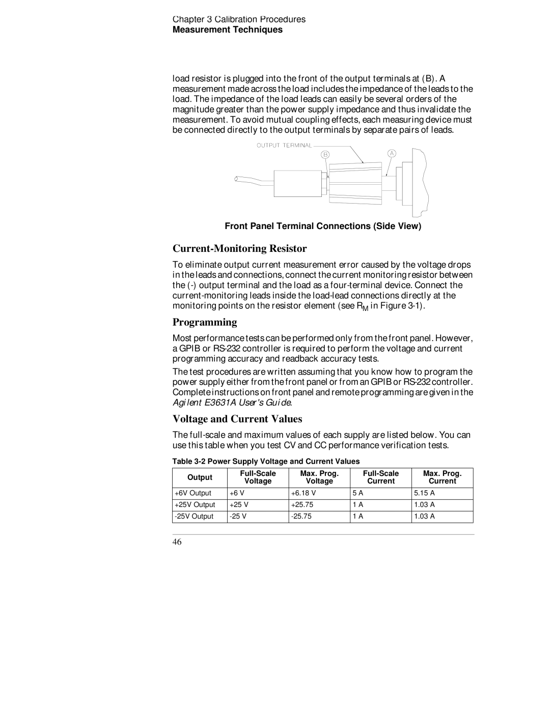
load resistor is plugged into the front of the output terminals at (B). A measurement made across the load includes the impedance of the leads to the load. The impedance of the load leads can easily be several orders of the magnitude greater than the power supply impedance and thus invalidate the measurement. To avoid mutual coupling effects, each measuring device must be connected directly to the output terminals by separate pairs of leads.
Front Panel Terminal Connections (Side View)
Current-Monitoring Resistor
To eliminate output current measurement error caused by the voltage drops in the leads and connections, connect the current monitoring resistor between the
Programming
Most performance tests can be performed only from the front panel. However, a GPIB or
The test procedures are written assuming that you know how to program the power supply either from the front panel or from an GPIB or
Voltage and Current Values
The
Table
Output | Max. Prog. | |||
Voltage | Voltage | Current | ||
| ||||
+6V Output | +6 V | +6.18 V | 5 A | |
+25V Output | +25 V | +25.75 | 1 A | |
1 A | ||||
|
|
|
|
Max. Prog.
Current
5.15A
1.03A
1.03A
46