Chapter 3 Calibration Procedures
Measurement Techniques
Measurement Techniques
Setup for Most Tests
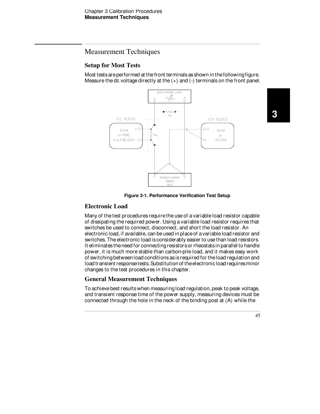
Most tests are performed at the front terminals as shown in the following figure. Measure the dc voltage directly at the (+) and
3
Figure 3-1. Performance Verification Test Setup
Electronic Load
Many of the test procedures require the use of a variable load resistor capable of dissipating the required power. Using a variable load resistor requires that switches be used to connect, disconnect, and short the load resistor. An electronic load, if available, can be used in place of a variable load resistor and switches. The electronic load is considerably easier to use than load resistors. It eliminates the need for connecting resistors or rheostats in parallel to handle power, it is much more stable than
General Measurement Techniques
To achieve best results when measuring load regulation, peak to peak voltage, and transient response time of the power supply, measuring devices must be connected through the hole in the neck of the binding post at (A) while the
45