Disassembly Procedures
!WARNING
To avoid risk of electrical shock, personal injury, or death, disconnect power to unit before servicing.
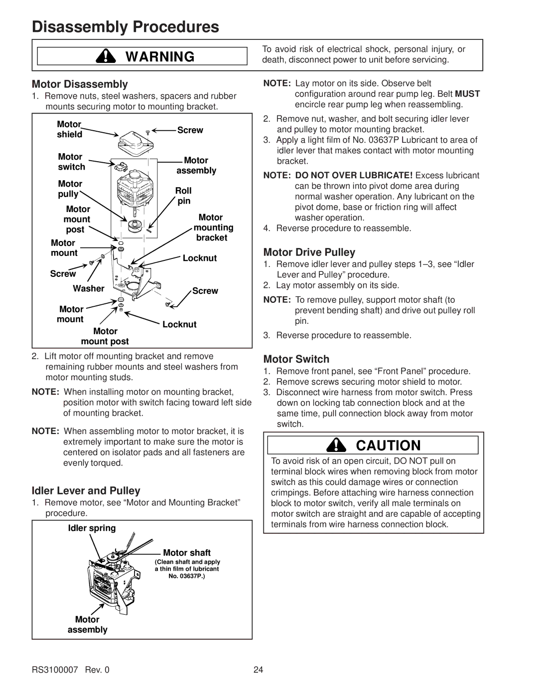
Motor Disassembly
1.Remove nuts, steel washers, spacers and rubber mounts securing motor to mounting bracket.
NOTE: Lay motor on its side. Observe belt configuration around rear pump leg. Belt MUST encircle rear pump leg when reassembling.
Motor | Screw | |
shield | ||
| ||
Motor | Motor | |
switch | ||
assembly | ||
| ||
Motor | Roll | |
pully | ||
pin | ||
Motor | ||
Motor | ||
mount | ||
post | mounting | |
Motor | bracket | |
| ||
mount | Locknut | |
| ||
Screw |
| |
Washer | Screw | |
Motor |
| |
mount | Locknut | |
Motor | ||
| ||
mount post |
|
2.Remove nut, washer, and bolt securing idler lever and pulley to motor mounting bracket.
3.Apply a light film of No. 03637P Lubricant to area of idler lever that makes contact with motor mounting bracket.
NOTE: DO NOT OVER LUBRICATE! Excess lubricant can be thrown into pivot dome area during normal washer operation. Any lubricant on the pivot dome, base or friction ring will affect washer operation.
4. Reverse procedure to reassemble.
Motor Drive Pulley
1.Remove idler lever and pulley steps
2.Lay motor assembly on its side.
NOTE: To remove pulley, support motor shaft (to prevent bending shaft) and drive out pulley roll pin.
3. Reverse procedure to reassemble.
2.Lift motor off mounting bracket and remove remaining rubber mounts and steel washers from motor mounting studs.
NOTE: When installing motor on mounting bracket, position motor with switch facing toward left side of mounting bracket.
NOTE: When assembling motor to motor bracket, it is extremely important to make sure the motor is centered on isolator pads and all fasteners are evenly torqued.
Idler Lever and Pulley
1.Remove motor, see “Motor and Mounting Bracket” procedure.
Idler spring |
Motor shaft |
(Clean shaft and apply |
a thin film of lubricant |
No. 03637P.) |
Motor |
assembly |
RS3100007 Rev. 0 |
Motor Switch
1.Remove front panel, see “Front Panel” procedure.
2.Remove screws securing motor shield to motor.
3.Disconnect wire harness from motor switch. Press down on locking tab connection block and at the same time, pull connection block away from motor switch.
!CAUTION
To avoid risk of an open circuit, DO NOT pull on terminal block wires when removing block from motor switch as this could damage wires or connection crimpings. Before attaching wire harness connection block to motor switch, verify all male terminals on motor switch are straight and are capable of accepting terminals from wire harness connection block.
24