Top Load Washer
Service
Table of Contents
Recognize Safety Symbols, Words, and Labels
Important Notices for Consumers and Servicers
Important Information
Important Safety Information
Grounding Instructions
General Information
Model Identification
Proper Grounding and Polarization of 120 Volts Wall Outlets
General Operation Definition
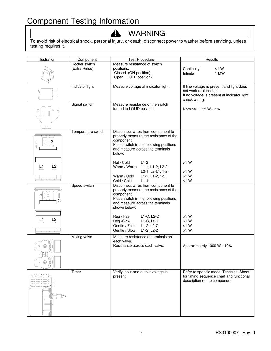
Component Test Procedure Results
Component Testing Information
Diagram and Schematic for correct
White Red Brown
Internal Motor Diagram and Schematic
Wire harness Connection Block White Brown Yellow Red Blue
Blue
Violet
Black White YellowBlue White/Black
Motor Assembly Three speed motor
No warm water Possible Cause Result
Troubleshooting Procedures
No hot water Possible Cause Result
No cold water Possible Cause Result
Motor does not operate Possible Cause Result
Timer does not advance Possible Cause Result
Constant agitation Possible Cause Result
No agitation Possible Cause Result
Constant spin Possible Cause Result
Slow spin or no spin Possible Cause Result
Possible Cause Result
Water leaking from outer tub Possible Cause Result
Washer locks-up or binding Possible Cause Result
Outer tub does not empty Possible Cause Result
Excessive vibration Possible Cause Result
Control Hood End Panels
Disassembly Procedures
Control Hood Assembly
Timer
Temperature and Speed Switch
Loading Door
Pressure Switch
Rocker Switch
Graphic Panel
Agitator
Agitator, Drive Bell and Seal Assembly
Installing Drive Bell
Front Panel
Service Access Panel
Motor and Mounting Bracket
Pump and Belt Removal
Reassembly of Pump and Belt
Pump Mounting screws Rear Pump leg Assembly
Embosses Motor Assembly
Idler Lever and Pulley
Motor Disassembly
Motor Switch
Motor Drive Pulley
Mixing Valve
Door Switch
Cabinet Top
Washtub and Balance Ring
Tub Cover and Gasket
Outer Tub
Drive Pulley, Helix and Brake
Weldment and Bearing Assembly
Upper Bearing Assembly
Transmission Assembly
Friction Ring
Appendix a
Installation Instructions
Tub Wall Unit
Standpipe
Prong grounded outlet only
Positionwasher and Level
Installation Summary
Longer Water Inlet Hoses
Adjustable leg Extension Kit
Observe all local codes and ordinances
Siphon Break Kit
Installation Requirements
Appendix B
Top Loading Washer
Thank you for buying an Amana washer
Recognize Safety Symbols, Words, Labels
Important Safety Information
Starting the Wash
Close washer lid
Starting the Wash contd
What do the little numbers mean?
Cycles
Dispensers
Clean softener dispenser after each use. Remove dispenser
Follow the Colors
Features, Hints, and Care
Cold Storage and Non-Use Periods
Moving and Storage
Topic Possible Cause Solution
Trouble Shooting
Water
Trouble Shooting contd
Repairs resulting from the following
Amana Washer Warranty
Appendix C
Top Loading Washer
Contents
Recognize Safety Symbols, Words, Labels
Important Safety Information
Save Time and Money
Asure Extended Service Plan
Parts and Accessories
Important Information Thank you for buying an Amana washer
Electrical Requirements
Before You Install
Water Supply Requirements
Risers
Washer Dimensions
Low Standpipe Installation
Location
HOT Cold
Wall Unit
Questions?
Warm/Cold
Operating Instructions Washer Control Panel
To Wash Clothes
Ex-Large Full
Operating Instructions
Bleach Dispenser
Helpful Hints and Features
Resetting Timer
Pauses
General Washer Care
Care and Cleaning
Safety Spin
Automatic Balance System
Topic Possible Cause Solution
Before Calling Service
Topic Possible Cause Solution
Vacations and Extended Non-Use
Cold Storage and Non-Use Periods
Cold Weather Care
Cold Weather Storage
Warranty Provides For
Warranty
Owner’s Responsibilities
See manual for details
Fast Track for Installing Washer