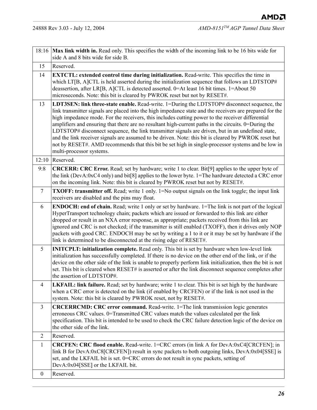
8151 specifications
The AMD 8151 is a notable member of AMD's family of chipsets, designed to complement the AMD K5 and K6 processors. Released in the late 1990s, this chipset was primarily targeted at performance-driven PCs. The AMD 8151 provided users with an array of features and technologies that enhanced the overall computing experience, making it a popular choice among system builders and enthusiasts at the time.One of the standout features of the AMD 8151 is its support for a 64-bit data bus. This significant design choice allowed for faster data transfer rates and better communication between the CPU and other critical components, such as memory. The chipset was capable of supporting multiple memory configurations, including ECC (Error-Correcting Code) memory, which enhanced system reliability, particularly for servers and workstations.
In terms of connectivity, the AMD 8151 included several integrated controllers, such as the PCI controller, which facilitated connections to various peripherals and expansion cards. With its support for the PCI bus, users could take advantage of high-speed devices, such as graphics cards, sound cards, and network adapters, enhancing the overall functionality of their systems.
Another important characteristic of the AMD 8151 is its power management capabilities. The chipset featured advanced power management technologies, which allowed systems to use energy more efficiently. This not only helped reduce operational costs but also contributed to less heat production, extending the longevity of the components within the PC.
The AMD 8151 also offered robust support for a range of bus speeds, which provided flexibility for users looking to customize their systems. With a maximum bus speed of 66 MHz, it was well-suited for the processors of its time, ensuring compatibility and optimal performance.
Moreover, the AMD 8151 played a crucial role in the development of 3D graphics capabilities. It was designed to work seamlessly with AMD's 3D graphics technology, which allowed for improved visual performance in gaming and multimedia applications. This made it an appealing choice for users who prioritized graphics performance.
Overall, the AMD 8151 chipset embodied the technological advancements of its era, providing enhanced performance, flexibility, and reliability. It stood as a testament to AMD's commitment to innovation in the computing space, marking a significant chapter in the evolution of PC architecture.

