Modero CV5
AMX Limited Warranty and Disclaimer
Table of Contents
Upgrading Modero Firmware
Programming
URL Resources 151
Introduction
CV5 Specifications
Specifications for 5 Widescreen Video Touch Panel
Supported Audio Sample
Viewing Angles
IR Reception Angle
Rates
Button Assignments
Included Accessories
Side Panel Components Cont
Operating / Storage
CV5 Panels Connector Layout
USB NXA-AVB/ETHERNET CAT5
Introduction Modero Widescreen Touch Panel
NXA-AVB/ETHERNET Breakout Box FG2254-10
Product Specifications
NXA-AVB/ETHERNET Specifications
Panels only
Installing the NXA-AVB/ETHERNET
Rear Components
Wiring the NXA-AVB/ETHERNET connectors and cables
NXA-AVB/ETHERNET Breakout Box connector wiring diagram
Wiring the NXA-AVB/ETHERNET for Unbalanced Audio
Wiring the NXA-AVB/ETHERNET for Balanced Audio
Balanced OUT
CV5 Touch Panel Accessories Modero Widescreen Touch Panel
Installing the No-Button Trim Ring
Unpacking the Panel
Button latch
Installing the Button Trim Ring
Removing the No-Button Trim Ring
Installing the Optional NXA-BEZ Colored Trim Ring Kits
NXA-BEZ Trim Ring Kits CV5
NXA-BEZ-5NB Trim Ring Kits without button openings
Installing the Button Bezel Kit NXA-BEZ-5B
Pre-Wall Installation of the Rough-In Box
Installing the No-Button Bezel Kit NXA-BEZ-5NB
Installation of an NXD Touch Panel
Installing the NXD panel within a Rough-In Box
Faceplate/Trim Ring Default Faceplate comes with buttons
Installing the NXD into drywall using Expansion Clips
NXD-CV5 Wall Mount panel dimensions using expansion clips
Installation
Installing the NXD into a Flat Surface using #4 screws
NXD-CV5 Wall Mount panel dimensions using #4 mounting screws
Mounting Tab Main CV5 unit Faceplate/Trim Ring
Installing an NXD-CV5 into a Rack Mount Kit NXA-RK5
Wiring a power connection
Wiring Guidelines for the CV5 Panels
Preparing captive wires
Ethernet RJ-45 Pinouts and Signals
Audio/Video Port Connections and Wiring
Ethernet/RJ-45 Port Connections and Wiring
Audio/Video RJ-45 Pinout Information
USB Port Connecting and Using Input Devices
RJ-45 wiring diagram
Panel Calibration
Calibrating the Modero Panel
Testing your Calibration
Touch Panel Calibration Screens
Configuring Communication
Modero Setup and System Connection
Modero connection information
Confirm the Installation of the USB Driver on the PC
Configuring and Using USB with a Virtual Master
Setup the Panel and PC for USB Communication
To setting up a USB connection to the panel
Confirm and View the current AMX USB device connections
Device Manager dialog showing USB device
USB
Assigning Communication Settings for a Virtual Master
Configuring a Wired Ethernet Connection
Using USB for Virtual Master communication
Configure the Panel’s Wired IP Settings
IP Settings section Configuring a Dhcp Address over Ethernet
Choose a Master Connection Mode Setting
Configure an Ethernet Connection Type
Obtained From NetLinx Master
These must match
Ethernet
URL List dialog
Using G4 Web Control to Interact with a G4 Panel
Resides on the same Subnet as itself
G4 Web Control
Using your NetLinx Master to control the G4 panel
Wireless Not available with the CV5 panel
Connection Details dialog
Configuring Communication Modero Widescreen Touch Panel
Configure the panel for a USB Connection Type
Upgrading the Modero Firmware via the USB port
Prepare NetLinx Studio for communication via the USB port
Confirm and Upgrade the firmware via the USB port
Default Modero panel value is
Panel firmware is shown on the right of the listed panel
Upgrading the Modero Firmware via Ethernet IP Address
Prepare the Master for communication via an IP
Prepare the panel for communication via an IP
Verify and Upgrade the panel firmware via an IP
NetLinx Workspace window showing connected Modero panel
Selected Firmware file
Setup Navigation Buttons
Protected Setup
Setup
Setup Page Elements
Inactivity Page Flip
Timeout
Information
Panel Brightness
Project Information
Project Information Page Elements
Panel Information
Panel Information Page Elements
Time & Date Setup
Time Display fields
Time & Date Setup Page Elements
Time Date Refresh/Set
Date Display fields
Master Volume
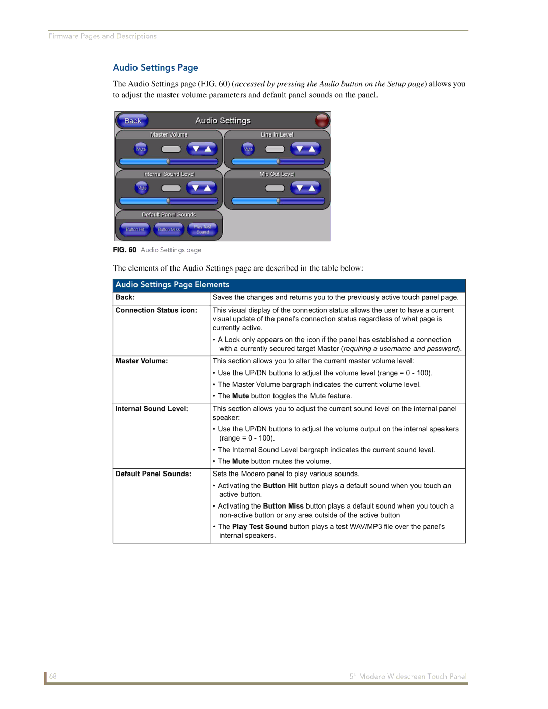
Audio Settings
Audio Settings Page Elements
Default Panel Sounds
Supported sampling rates for WAV
Video Adjustment
Volume Page Elements
Supported WAV Sampling Rates
Video Setup Page Elements
Protected Setup Navigation Buttons
Protected Setup Navigation Buttons
Device Number
Protected Setup Page Elements
Reboot Panel
Options
System Recovery
Slider
IP Settings
System Settings
System Settings Page Elements
Full Duplex
System Connection Page Elements
Master Connection
Calibration
Calibration page actually 3 separate screens
G4 Web Control Page Elements
G4 Web Control Settings
G4 Web Control
Sensor Setup
G4 Web Control Timeout
Light Sensor
Sensor Setup Page Elements
Dim Mode Minimum
Light Level field
Sense
Motion Sensor
Wake Panel On Motion
Other Settings
Other Settings menu
Image Caching Page Elements
Image Cache Settings
Image Caching
Clear Cache
Setting the image cache
Enable
Image Cache Status
Checking image cache status
Password Settings
Clearing the image cache
Change
Password Settings
Panel Password
Tools
Panel Logs
Clearing the Panel Connections Log
Checking the Panel Connection Logs
Refreshing the Panel Connections Log
Panel Logs
Panel Statistics
Panel Statistics
Clearing the Panel Statistics
Checking the Panel Statistics
Refreshing the Panel Statistics
Ethernet Statistics
Connection Utility
Connection Utility
Using the Connection Utility
Secondary Connection
Page
Button Assignments
Commands
Commands
@APG
@PHE
@DPG
@PDR
@PHP
Commands
@PPT
@PPM
@PPN
@PPX
@PST
@PSE
@PSP
Ppon
Ppof
Ppog
RGB Values for all 88 Basic Colors
Programming Numbers
RGB triplets and names for basic 88 colors
Index No Name Red Green Blue
100 Modero Widescreen Touch Panel
Font ID # Font type Size
Default Font Styles and ID Numbers
Font styles and ID numbers
TPD4 Border Styles by Name
Border styles and Programming numbers
Border Styles and Programming Numbers
Border styles
Modero Widescreen Touch Panel 103
Button Commands
APF
Button Commands
ANI
BAT
BCB
BCF
BFB
BCT
BDO
BLN
BIM
Entry is required
Sendcommand Panel,BMC-150,1,1,315,1,%BR%FT%TX%BM%IC%CF%CT
BMC
BMF
BMF-vt addr range,button states range,data
Cont
BMP
BMI
BML
BNC
BOP
BNN
BNT
BPP
BOR
BOS
BSM
BRD
BSF
BSO
BVP
BVL
BVN
BVT
ENA
CPF
DPF
FON
GLH
GDI
GIV
GLL
GSC
GRD
GRU
GSN
JSI
ICO
JSB
Pass data
JST
MBT
MDC
Effect names
TEC
TEF
TXT
UNI
Sendcommand Panel,UNI-500,1,0041
Sendcommand TP,UNI-1,0,0041
UNI-vt addr range,button states range,unicode text
Text Effect Names
Text Effects
Button Query Commands
Defineevent
Field Description
Button Query Commands
Custom Event Fields
?BCB
?BCF
?BCT
?BMP
?BOP
?BRD
?BWW
?FON
?ICO
?JSB
?JSI
?JST
?TEC
?TEF
Send Command Panel,?TEF-529,1
Send Command Panel,?TXT-529,1
?TEF-vt addr range,button states range
Panel Runtime Operation Commands
Panel Runtime Operations
Beep
@AKP
@AKR
Brit
Pkeyp
Setup
@EKP
@PKP
Tpageon
@SOU
@TKP
Tpageoff
CAL
Input Commands
Input Commands
KPS
Decimal numbers Hexidecimal values Virtual keystroke
Embedded codes
Embedded Codes
Panel Setup Commands
Panel Setup Commands
Dynamic Image Commands
Dynamic Image Commands
RAF-resource name,data
Troubleshooting Information
My Workspace window
Symptom Solution My Modero panel isn’t appearing
Connecting
My Modero panel can’t obtain a
Calibration is not working
Symptom Solution My on-screen mouse cursor
Doesn’t appear
Panel doesn’t respond to my
Only one shows up
Symptom Solution
Connected to my System Master
After downloading a panel file or
Formatting Code Operations
Text Formatting Codes for Bargraphs/Joysticks
Bargraph Text Code Inputs
Example
Character Types
Text Area Input Masking
Input mask character types
Character Masking Rule
Input mask operations
Input mask ranges
Input mask next field characters
Input mask literals
Common Name Input Mask
Input mask output examples
Output Examples
Escape Sequences
URL Resources
Special escape sequences
Sequence Panel Information
Appendix a 152 Modero Widescreen Touch Panel
Appendix a Modero Widescreen Touch Panel 153
Appendix a 154 Modero Widescreen Touch Panel
Appendix a Modero Widescreen Touch Panels 155
It’s Your World Take Control