Chapter 4: E2 Controller

4.6.2.2 Configure the Controller (I/O Board) pLAN Address

Immediately after turning power back on, press and hold the Alarm and the up-arrow keys simultaneously for 10 to 15 seconds. First you will see a display message “self test please wait” then the pLAN Address Configuration screen shown below will appear. Don’t press the Enter key; the cursor is already in the modifiable field.

Figure 4-70. pLAN Address screen.

Press the up-arrow key to set the pLAN address (1–8) for the controller (I/O board). The pLAN Address 1 is already assigned by default to the first (lead) controller in the group. Address 2 is to be assigned to the first controller added to the group (Address 3 is to be assigned to the second controller added and so on). Then press the Enter key to confirm your selection. A message “NO LINK” will appear.

Next, press the up-arrow , down-arrow , and Enter keys simultaneously. Reconfigure the terminal address following the steps in Section 4.6.2 again. This time set the terminal address to match the corresponding controller (I/O board) address. If the controller is assigned Address 2, then the corresponding terminal address should be set to 31 as shown in Table 4-11. If the next controller is assigned Address 3, the corresponding terminal should be set to 30.

After setting the correct terminal address, press the Enter key once to confirm your selection. A message “NO LINK” will appear. At this point, the terminal has been set with the correct address for the controller, and the controller has been set for the terminal—but now they need to be assigned to each other.

4.6.2.3 Assign the Terminal to the Controller

1.Access the Terminal Address Configuration screen again using the up-arrow , down-arrow , and Enter keys.

2.Press the Enter key until the cursor moves to the field “I/O board address:__”.

3.Using the up and down-arrow keys, enter the address (1–8) for the controller I/O board.

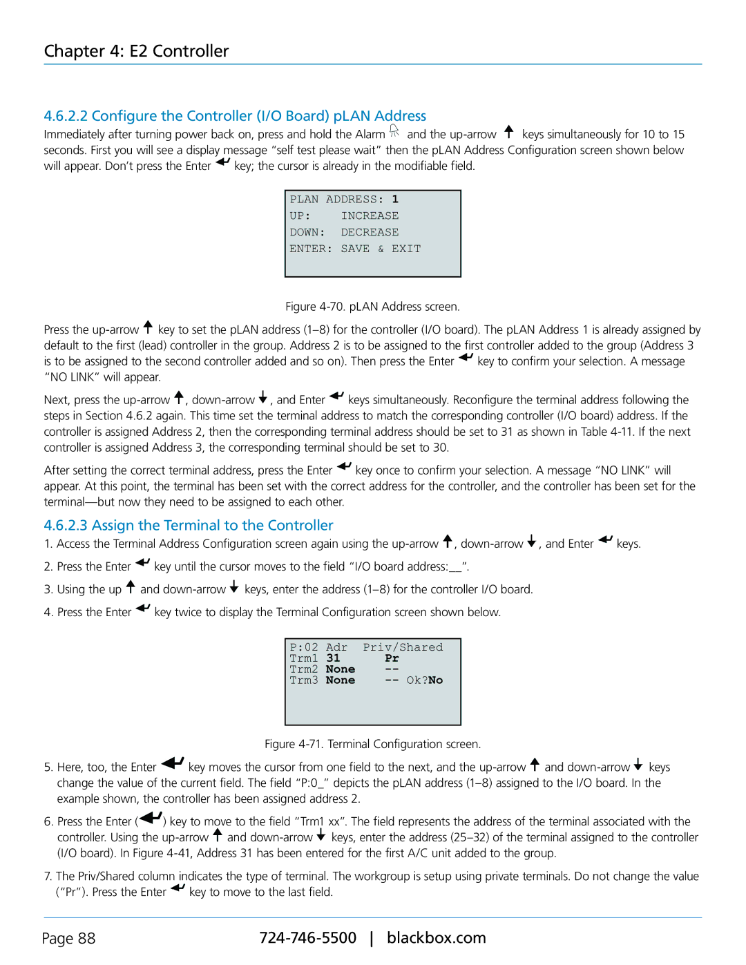
4.Press the Enter key twice to display the Terminal Configuration screen shown below.

Figure 4-71. Terminal Configuration screen.

5.Here, too, the Enter key moves the cursor from one field to the next, and the up-arrow and down-arrow keys change the value of the current field. The field “P:0_” depicts the pLAN address (1–8) assigned to the I/O board. In the example shown, the controller has been assigned address 2.

6.Press the Enter () key to move to the field “Trm1 xx”. The field represents the address of the terminal associated with the controller. Using the up-arrow and down-arrow keys, enter the address (25–32) of the terminal assigned to the controller (I/O board). In Figure 4-41, Address 31 has been entered for the first A/C unit added to the group.

7.The Priv/Shared column indicates the type of terminal. The workgroup is setup using private terminals. Do not change the value (“Pr”). Press the Enter key to move to the last field.

Page 88

724-746-5500 blackbox.com

Page 88
Image 88
Black Box CRDX-G-FS-12KW user manual Configure the Controller I/O Board pLAN Address, Assign the Terminal to the Controller

CRDX-W-FS-12KW, Black Box Cold Row DX, CRDX-W-FS-24KW, CRDX-A-FS-24KW, CRDX-A-FS-12KW specifications

The Black Box CRDX series consists of high-performance cooling solutions designed to maintain optimal temperature conditions in data centers and server rooms. Key models in this series include the CRDX-W-FS-12KW, CRDX-W-FS-24KW, CRDX-G-FS-12KW, and CRDX-A-FS-24KW. These units are engineered to provide efficient cooling while addressing the rising demands of modern IT infrastructure.

One of the standout features of the CRDX series is its cold row design. This configuration enables targeted cooling delivery directly to the equipment, enhancing efficiency and reducing energy consumption. The airflow management in these models ensures that cooled air is directed where it is needed most, minimizing hotspots and maximizing cooling performance.

Both the CRDX-W-FS-12KW and CRDX-W-FS-24KW models utilize advanced refrigerant-based cooling technology. These units are equipped with electronically commutated (EC) fans, which are highly efficient and quieter than traditional fan technologies. This innovation not only lowers operational costs but also creates a more comfortable environment within the data center.

The CRDX-G-FS-12KW model stands out for its hybrid capabilities, offering both chilled water and direct expansion cooling options. This versatility allows facility managers to choose the best cooling approach based on their specific requirements and current infrastructure. The hybrid system can optimize energy consumption and enhance cooling efficiency, contributing to lower operating costs.

Another noteworthy feature across these models is their intelligent controls and monitoring capabilities. Equipped with sophisticated sensors and control systems, operators can gain real-time insights into temperature fluctuations, humidity levels, and unit performance. This data aids in proactive maintenance and ensures that cooling systems are operating at peak efficiency.

The CRDX-A-FS-24KW, on the other hand, is designed with a focus on adaptability and scalability. This model can be integrated easily into existing network setups, making it an excellent choice for facilities that anticipate future growth or need to adapt to changing cooling demands.

Overall, the Black Box CRDX series exemplifies the latest advancements in cooling technology, offering innovative features designed to support high-density computing environments. With their efficient cooling capabilities, intelligent controls, and flexible design options, these models provide reliable solutions for data centers looking to enhance their cooling systems while reducing operating costs.