Manuals
/
Black Box
/
Computer Equipment
/
Network Hardware
Black Box
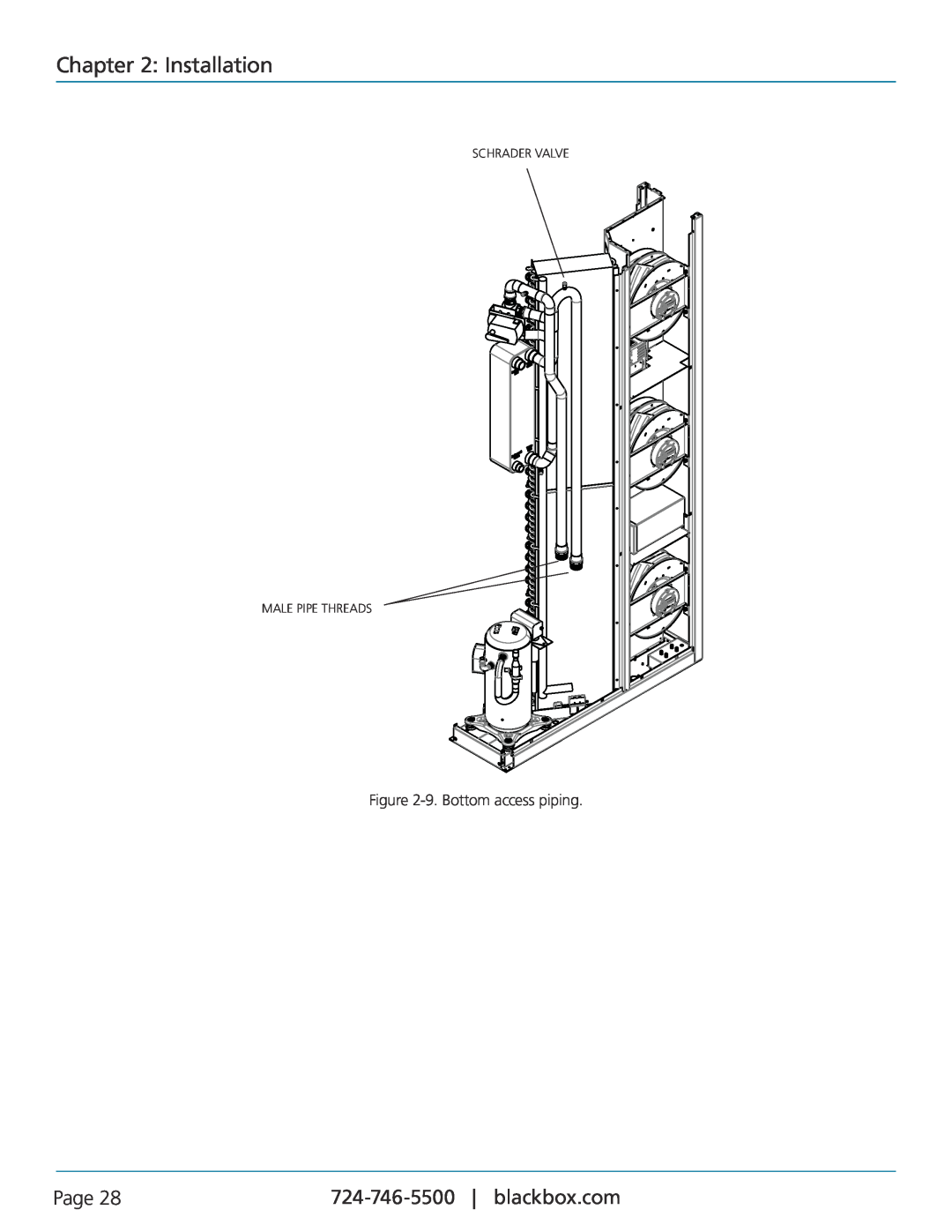
CRDX-W-FS-12KW, CRDX-A-FS-24KW user manual Installation, Page, 9. Bottom access piping
Models:
CRDX-W-FS-12KW
Black Box Cold Row DX
CRDX-W-FS-24KW
CRDX-A-FS-24KW
CRDX-A-FS-12KW
CRDX-G-FS-12KW
CRDX-G-FS-24KW
1
28
132
132
Download
132 pages
49.93 Kb
25
26
27
28
29
30
31
32
<
>
Troubleshooting
Install
7. Typical W/G piping diagram
Mounting/Placement
Warranty
Maintenance
Features 4.1.1.1 Field Configurable
Symptom Control is erratic
Temp Zone Setup
System Charging Procedures
Page 28
Image 28
Chapter 2: Installation
SCHRADER VALVE
MALE PIPE THREADS
Figure
2-9.
Bottom access piping.
Page 28
724-746-5500
blackbox.com
Page 27
Page 29
Page 28
Image 28
Page 27
Page 29
Contents
Cold Row DX User Manual
CRDX-A-FS-24KW CRDX-G-FS-12KW CRDX-A-FS-12KW CRDX-W-FS-24KW
CRDX-G-FS-24KW CRDX-W-FS-12KW
Customer Support Information
Page
Trademarks Used in this Manual
Trademarks Used in this Manual
FCC and IC RFI Statements
Page
Normas Oficiales Mexicanas Electrical Safety Statement
NOM Statement
Instrucciones de Seguridad
Page
Table of Contents
Table of Contents
Page
Page
Table of Contents
Water-Cooled Systems CRDX-W-FS-12KW, CRDX-W-FS-24KW
Table of Contents
Page
Table of Contents
Page
Table of Contents
Page
Chapter 1 Introduction
1. Introduction 1.1 General
1.2 Product Description
Page
Page
Chapter 1 Introduction
Figure 1-1. User interface display
12-Month Precision A/C Limited Warranty
24-Month Precision A/C Upgraded Limited Warranty
Chapter 1 Introduction
Page
1.3 Product Warranty
Cold Row Warranty - Compressor
Chapter 1 Introduction
Page
1.4.2 Safety Summary
1.4 Safety 1.4.1 General
Chapter 1 Introduction
Page
Chapter 1 Introduction
Never work on electrical equipment unless another person who is familiar with the operation and hazards of the equipment and is competent in administering first aid is nearby
Page
Chapter 1 Introduction
1.5 General Design
Page
1.5.1 Electrical Compartment
1.5.2 Circuit Breakers/Motor Start Protectors
1.5.3 Compressor
1.5.3.1 Electronic Thermal Expansion Valve
1.5.7 Temperature/Humidity Sensors
1.6.1 Remote Mounted Supply Temperature/Humidity Sensor
1.6 Optional Equipment
1.6.2 Water Detector
Chapter 2 Installation
2. Installation 2.1 Receiving the Equipment
2.2 Moving the Equipment
2.3 Site Preparation
2.4 Mounting/Placement
Conditioned Space
Chapter 2 Installation
Page
Chapter 2 Installation
2.5 Air Distribution
Page
Page
Chapter 2 Installation
Figure 2-2. Typical air distribution
2.6 Optional Equipment Field Installed
2.6.1 Remote Water Detectors
Chapter 2 Installation
Page
Chapter 2 Installation
2.6.2 Remote Temperature/Humidity Sensor
Page
2.6.3 Outdoor Condensers
Chapter 2 Installation
Figure 2-7. Typical W/G piping diagram
Page
Chapter 2 Installation
Piping Connections
Page
Water-Water/Glycol Supply and Return Piping Connections
Chapter 2 Installation
Figure 2-8. Top access piping
Page
Chapter 2 Installation
Figure 2-9. Bottom access piping
Page
SCHRADER VALVE MALE PIPE THREADS
2.8 Split Air-Cooled Systems
2.8.1 Refrigerant Piping
Chapter 2 Installation
Page
Chapter 2 Installation
2.8.1.1 DX Refrigerant Piping Connections
Page
2.8.1.2 Refrigerant Pipe Sizing
2.8.2 Remote Air-Cooled Condensers
Chapter 2 Installation
Page
2.9 Utility Connections 2.9.1 Main Power
2.8.3 Condensate Drain Line
Chapter 2 Installation
Page
Page
Chapter 2 Installation
Figure 2-12. Sample nameplate
2.9.1.1 Single-Phase Units 208/230
2.9.1.2 Three-Phase Units
2.9.2.2 Remote Temperature/Humidity Sensor
2.9.2 Optional Equipment
2.9.3.2 Glycol-Cooled Systems CRDX-G-FS-12KW, CRDX-G-FS-24KW
2.9.3.3 Remote Condenser CRDX-A-FS-12KW, CRDX-A-FS-24KW
Chapter 2 Installation
Page
2.10 System Charging Procedures
2.10.1 Water-Water/Glycol Cooled Systems
2.10.2 Remote Air-Cooled Systems
Chapter 2 Installation
Chapter 2 Installation
2.10.2.1 Estimating Refrigerant Charge
Page
2.10.2.2 Preparing System For Charging
Evacuate the System
Chapter 2 Installation
Page
2.10.2.3 Refrigerant Charging Procedures
Fine-Tuning the System Charge
Initial System Charge
Chapter 2 Installation
Chapter 2 Installation
2.10.2.4 -30 F Ambient Applications
Page
Chapter 2 Installation
2.10.3.2 Saturated Refrigerant Pressure
Page
2.11 Settings and Adjustments 2.11.1 Water-Water/Glycol Circuit
2.11.2 Low-/High-Pressure Limit Switch
2.11.3 Thermal Expansion Valve
2.11.4 Hot Gas Bypass
Chapter 3 Startup/Commissioning
3. Startup/Commissioning 3.1 Initial Operation
3.2 Step-by-Step Startup Instructions
3.3 Microprocessor Controller Programming
4.1.1 Features 4.1.1.1 Field Configurable
4.1.1.2 Password Protection
Chapter 4 E2 Controller
4. E2 Controller 4.1 General
4.1.2 User Interface Display Panel
4.1.2.1 Function Keys
Chapter 4 E2 Controller
Page
4.1.2.2 Contrast Adjustment
4.1.2.3 Alarms
4.1.3 Controller I/O Module
Controller I/O Module Layout
Chapter 4 E2 Controller
4.1.4 BMS Interface
Page
4.2 Navigating Controller Display Screens 4.2.1 Menu Selection
4.2.2 Menus
Chapter 4 E2 Controller
Page
4.2.3 Display Variables
4.2.4 Cursor Position in Screens
Chapter 4 E2 Controller
Page
4.2.6 Password Authorization Levels
4.2.6.1 Password-Protected Screen
4.2.5 Modifiable Variables
Chapter 4 E2 Controller
4.2.6.2 Wrong Password
4.2.6.3 Setting the Passwords
4.3 System Operation
Chapter 4 E2 Controller
Chapter 4 E2 Controller
4.3.1 Setpoint Adjustment
Page
Page
Chapter 4 E2 Controller
Figure 4-14. Flashing cursor
4.3.2 Alarms
4.3.2.1 Summary Alarm
4.3.2.2 Customer Alarms
4.3.2.3 Custom Alarms
4.4.1 Control Signals
4.4.1.1 On/Off Digital Control
Chapter 4 E2 Controller
Page
4.4.2.1 Temperature/RH Control
4.4.1.2 Proportional/Integral P/I Control
4.4.2 Control Methods
4.4.2.2 Dewpoint Control
4.4.3 Operating Configurations
4.4.3.1 Compressor Operation
Chapter 4 E2 Controller
Page
4.4.3.2 Water-W/G Operation
4.4.3.3 Dehumidifying
4.4.4 Airflow/Fan Speed Control
Chapter 4 E2 Controller
4.4.4.3 Temperature Proportionate Speed Control
4.4.4.1 Independent Fan Speed Control
4.4.4.2 Variance from Average Fan Speed Control
4.4.4.4 Manual Speed Control
Chapter 4 E2 Controller
“Control” allows modification of basic control parameters such as setpoints and clock. Level 1 password is needed to enter this menu
Page
4.5.2.2 Return Temperature Sensor
4.5.2.4 Temperature Sensors
4.5.2 Information Menu Loop
4.5.2.1 Operating Conditions
4.5.2.5 Remote Supply Temperature/Humidity Sensor
4.5.2.6 Discharge Pressure
4.5.2.7 Setpoint Values
4.5.2.8 Compressor Status
4.5.2.10 EHGB Status
4.5.2.11 Fan Status
4.5.2.12 Group Information Menu Screens
4.5.2.13 Software Version/Date
4.5.3 Alarm Log
4.5.3.1 Alarms
4.5.3.2 Non-Critical Alarms
4.5.3.3 Critical Alarms
4.5.3.4 Alarm Screen Messages
Table 4-3. Alarm screen messages
Chapter 4 E2 Controller
Page
Chapter 4 E2 Controller
4.5.4 Control Menu Loop
Page
Chapter 4 E2 Controller
4.5.4.1 Setpoint Screens
Page
Chapter 4 E2 Controller
4.5.4.2 Alarm Setpoint Screens
Page
Chapter 4 E2 Controller
Figure 4-33. Low humidity alarm
Page
Dirty Filter Timer
4.5.5 Service Menu Loop
4.5.4.3 Clock Screen
Chapter 4 E2 Controller
4.5.5.1 Humidity
Figure 4-40. Service menu loop selections
Chapter 4 E2 Controller
Page
Chapter 4 E2 Controller
4.5.5.2 Alarms
Page
Chapter 4 E2 Controller
4.5.5.3 Sensors
Page
Temp Zone Setup
Blower Setup
4.5.5.4 Blower
Chapter 4 E2 Controller
4.5.5.5 Options Menu Loop
Control, Startup
Chapter 4 E2 Controller
Page
Unit Timers
T/H Offset Scaling
Chapter 4 E2 Controller
Page
Custom Setup
Customer Alarm Input Optional
Chapter 4 E2 Controller
Page
Chapter 4 E2 Controller
Custom Alarm Setup Optional
Page
Table 4-5. Alarms 9 to
Table 4-6. Alarms 17 to
Chapter 4 E2 Controller
Page
Table 4-7. Alarms 25 to 32 Sensor failure alarms
Table 4-8. Alarms 33 to 40 Sensor failure alarms
Chapter 4 E2 Controller
Page
Chapter 4 E2 Controller
Workgroup Screens
Page
4.5.5.6 Digital In
4.5.5.7 Run Hours
Chapter 4 E2 Controller
Page
4.5.5.9 Save Configuration
4.5.5.8 BMS Communications
Chapter 4 E2 Controller
Page
Chapter 4 E2 Controller
4.5.5.10 Factory Menu
Page
4.6.1 Workgroup Setup
4.6 Communication with the Controller
Chapter 4 E2 Controller
Page
4.6.1.4 Out of Service
4.6.2 Configuring a Workgroup
4.6.1.1 Standby
4.6.1.2 Capacity Assist
Chapter 4 E2 Controller
4.6.2.1 Configure the Terminal Address
Page
4.6.2.2 Configure the Controller I/O Board pLAN Address
4.6.2.3 Assign the Terminal to the Controller
Chapter 4 E2 Controller
Page
4.6.2.4 Fault Messages
4.6.2.5 Displaying the Network Status and Firmware Version
Chapter 4 E2 Controller
Page
Chapter 4 E2 Controller
4.6.2.6 Configure Workgroups
Page
Figure 4-76. FactoryGroupsGroups Config Screen 1. See Table
Table 4-12. FactoryGroupsGroups Config Screen 1 parameters
Chapter 4 E2 Controller
Page
Page
Chapter 4 E2 Controller
Table 4-13. FactoryGroupGroup Rotation Screen 2 parameters
Page
Chapter 4 E2 Controller
Table 4-15. FactoryGroupCapacity Assist Screen 4 parameters
Table 4-17. Group alarms 1 to
Table 4-18. Group alarms 9 to
Chapter 4 E2 Controller
Page
Table 4-19. Group alarms 17 to
Table 4-20. Group alarms 25 to
Chapter 4 E2 Controller
Page
Chapter 4 E2 Controller
Table 4-21. Group alarms 33 to
Page
4.6.2.7 ServiceOptionsGroup Menu Screens
Group Setup
Chapter 4 E2 Controller
Page
Capacity Assist
Capacity Assist #2
Group Sensors
Chapter 4 E2 Controller
Group Averaging
4.6.2.8 Group Information Menu Screens
Chapter 4 E2 Controller
Page
Group Alarms
Group Sensor Values
Lead Controller Group Sensors
Group Sensor Status
Chapter 4 E2 Controller
4.7 BMS Communications
Page
4.7.1 Direct BMS Control
4.7.2 BMS Communication
Chapter 4 E2 Controller
Page
4.8 Troubleshooting the Control I/O Module Signal LEDs
Table 4-26. I/O control module signal LEDs
Chapter 4 E2 Controller
Page
4.9 BMS Parameters, Version
Chapter 4 E2 Controller
Page
Table 4-27. BMS parameters
Chapter 4 E2 Controller
Page
Page
Chapter 4 E2 Controller
Type of unit valid numbers 0 to 6 See
Variable/Value Descriptions
Chapter 4 E2 Controller
Page
Table 4-30. Variable/Value Descriptions
4.9.4 Alarm Packed Bit Variables
Table 4-32. Alarm-Packed Bit Variables
Chapter 4 E2 Controller
Page
4.9.5 Sensor Failure Packed Bit Variables
Chapter 4 E2 Controller
Page
Table 4-33. Sensor Failure Packed Bit Variables
4.9.6 Digital Input Packed Bit Variables
Chapter 4 E2 Controller
Page
Table 4-34. Digital Input Packed Bit Variables
4.9.7 Digital Output Packed Bit Variables
Chapter 4 E2 Controller
Page
Table 4-35. Digital Output Packed Bit Variables
Page
Chapter 4 E2 Controller
4.9.8 Unsigned Values for HTTP, SNMP/Modbus Holding Registers/Analog Values for BACnet
Chapter 5 Maintenance
5. Maintenance 5.1 Periodic General Maintenance
5.1.1.1 Cleanable Filters
5.1.1 Filters
F Fgure 5-1. Cleanable filters
Chapter 5 Maintenance
Page
5.1.1.2 Cartridge Filters
5.1.2 EC Fans
5.1.3 Coil
5.1.4 Drain Pans
5.2 Troubleshooting
5.1.6 A/C System
Chapter 5 Maintenance
Page
Symptom Control is erratic
Chapter 5 Maintenance
Page
Chapter 5 Maintenance
Page
5.3 Field Service
5.3.1 Water-Water/Glycol System
Leak Detection/Repair
5.3.2 DX System
5.3.2.3 Refrigerant Piping
5.3.3 Refrigeration System Repairs 5.3.3.1 Compressor Failure
Chapter 5 Maintenance
Page
5.3.3.2 Standard Cleanout Procedure
5.3.3.3 Burn-Out/Acidic Cleanup Procedure
5.3.4 Component Replacement
5.3.4.1 Fan Replacement
Chapter 5 Maintenance
5.3.4.2 Condensate Pump Replacement
Page
Chapter 6 Troubleshooting
6. Troubleshooting
6.2 Obtaining Warranty Parts
6.3 Obtaining Spare/Replacement Parts
Page
Chapter 6 Troubleshooting
Quotes are given for specified listed parts for a specific unit
A.1 Checklist for Completed Installation of Cold Row DX
Appendix A Forms
Appendix A. Forms
Page
Page
Appendix A Forms
Date
Appendix B. Glossary Definition of Terms and Acronyms
Appendix B Glossary Definition of Terms and Acronyms
Page
Page
Appendix B Glossary Definition of Terms and Acronyms
VDC Volt, direct current WG Water Glycol
Page
Page
Page
Tech support the way it should be
Black Box Tech Support FREE! Live. 24/7
About Black Box