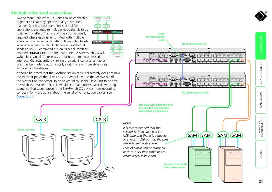
Multiple video head connections
Two or more ServSwitch CX units can be connected | REMOTEREMOTE | ||
together so that they operate in a synchronised | USER | USER | |
|
|
| |
manner. Synchronised operation is useful for | CX R | CX R | |
applications that require multiple video signals to be |
|
|
|
switched together. This type of operation is usually |
|
| |
|
|
| |
required where each server is fitted with multiple |
|
|
|
video cards or video cards with multiple video heads. |
|
| |
|
| ||
Whenever a ServSwitch CX channel is switched, it |
|
|
|
sends an RS232 command out on its serial interface
(marked COM1/UPGRADE on the rear panel). A ServSwitch CX will switch its channel if it receives the same command on its serial interface. Consequently, by linking the serial interfaces, a master unit may be made to automatically switch one or more slave units as shown in the diagram.
SAM SAM
SERVER
SYSTEM
|
|
|
| Serial |
|
|
|
|
|
|
|
|
|
|
|
|
|
|
|
|
| synchronisation |
|
|
|
|
|
|
|
|
|
|
|
|
|
|
|
| |||
|
|
|
| cable |
|
|
|
|
|
|
|
|
|
|
|
|
|
|
|
|
|
|
|
|
|
|
| Slave ServSwitch CX |
|
|
|
|
|
|
|
|
| ||||
Made in |
| WARNING |
| CATx USER PORTS | POWER CONTROL | COM1 / UPGRADE | COM2 / MODEM | COMPUTER CONNECTIONS | COMPUTER CONNECTIONS |
| COMPUTER CONNECTIONS |
| ||||||||
|
| 4 | 2 |
|
|
| 24 | 23 | 22 | 21 | 16 | 15 | 14 | 13 | 8 | 7 | 6 | 5 | ||
the U.K. |
| !RJ45 CONNECTORS ON THIS |
|
|
| |||||||||||||||
|
| PANEL ARE FOR CONNECTION |
|
|
|
|
|
|
|
|
|
|
|
|
|
|
|
|
| |
|
| TO KVM EQUIPMENT ONLY. |
|
|
|
|
|
|
|
|
|
|
|
|
|
|
|
|
| |
|
| DO NOT CONNECT TO NETWORK OR |
|
|
|
|
|
|
|
|
|
|
|
|
|
|
|
|
| |
|
| TELEPHONE SYSTEMS |
|
|
|
| USER PORT 1 |
|
|
|
|
|
|
|
|
|
|
|
|
|
|
|
| OPTIONS |
|
|
|
|
|
|
|
|
|
|
|
|
|
|
| ||
| 5V | 5V |
|
|
|
|
|
|
|
|
|
|
|
|
|
|
|
| ||
| 4A | 4A | 1 2 3 4 |
|
|
|
|
|
|
|
|
|
|
|
|
|
|
|
|
|
|
|
| ON |
|
|
|
|
|
|
|
|
|
|
|
|
|
|
|
|
|
Indoor use only | MAIN PWR IN | AUX PWR IN |
| 3 | 1 |
|
| KM | 20 | 19 | 18 | 17 | 12 | 11 | 10 | 9 | 4 | 3 | 2 | 1 |
®
It should be noted that the synchronisation cable deliberately does not have the transmit pin of the Slave End connector linked to the receive pin of the Master End connector. To do so would cause the Slave unit to be able to switch the Master unit. This would setup an endless cyclical switching sequence that would prevent the ServSwitch CX devices from operating correctly. For more details about the serial synchronisation cables, see Appendix 7.
Made in | WARNING |
| CATx USER PORTS | POWER CONTROL | COM1 / UPGRADE | COM2 / MODEM | COMPUTER CONNECTIONS | COMPUTER CONNECTIONS |
| COMPUTER CONNECTIONS |
| ||||||||
the U.K. | !RJ45 CONNECTORS ON THIS | 4 | 2 |
|
|
| 24 | 23 | 22 | 21 | 16 | 15 | 14 | 13 | 8 | 7 | 6 | 5 | |
| PANEL ARE FOR CONNECTION |
|
|
|
|
|
|
|
|
|
|
|
|
|
|
|
|
| |
| TO KVM EQUIPMENT ONLY. |
|
|
|
|
|
|
|
|
|
|
|
|
|
|
|
|
| |
| DO NOT CONNECT TO NETWORK OR |
|
|
|
|
|
|
|
|
|
|
|
|
|
|
|
|
| |
| TELEPHONE SYSTEMS |
|
|
|
| USER PORT 1 |
|
|
|
|
|
|
|
|
|
|
|
|
|
|
| OPTIONS |
|
|
|
|
|
|
|
|
|
|
|
|
|
|
|
| |
5V | 5V |
|
|
|
|
|
|
|
|
|
|
|
|
|
|
|
|
| |
4A | 4A | 1 2 3 4 |
|
|
|
|
|
|
|
|
|
|
|
|
|
|
|
|
|
|
| ON |
|
|
|
|
|
|
|
|
|
|
|
|
|
|
|
|
|
Indoor use only | MAIN PWR IN | AUX PWR IN | 3 | 1 | KM | 20 | 19 | 18 | 17 | 12 | 11 | 10 | 9 | 4 | 3 | 2 | 1 |
Master ServSwitch CX
The local user ports can also be used to view multiple video head installations.
CX R | CX R |
Slave monitor | Master monitor |
Notes
It is recommended that the
second SAM in each pair is a
server to derive its power.
Pairs of SAMs can be strapped
Servers fitted with dual video heads
21