MIC612 Thermal Camera
Page
Table of Contents
On-Screen Display OSD Menus Bosch Protocol
Common User Commands
Advanced Features
On-Screen Display OSD Menus Pelco Protocol
Maintenance and Troubleshooting Keyboard Commands By Number
Index
About this Manual
Safety
Important Safety Instructions
Conventions in this Manual
MIC612 Thermal Camera Safety en
EC Directives
Important Notices
Coax grounding
FCC ET Ices Information commercial applications
FCC and Ices Compliance
Informations FCC ET Ices applications commerciales
Bosch Notices
Customer Support and Service
USA
Additional Products Required
Parts List
2Unpacking
Additional Tools Required
Installation Overview
MIC camera mounting positions Upright, Inverted
Typical Mounting Arrangements
Number Description
Mounting Positions
Alarm Card Number Installed? Alarm Inputs Alarm Outputs
About Alarm Inputs and Outputs
An 8-input alarm card installed in the MIC PSU
3About the MIC Shielded Composite Cable
Typical Installation Configurations
Installation
MIC-BP4 sold separately
Example 2 Configuration with RS-485 protocol connection
Overview of Installation Steps
Follow these steps in sequence to install the MIC612 camera
Mounting the Camera
Installing the MIC Power Supply Unit PSU
Earth Link on PCB
Fuse Ratings
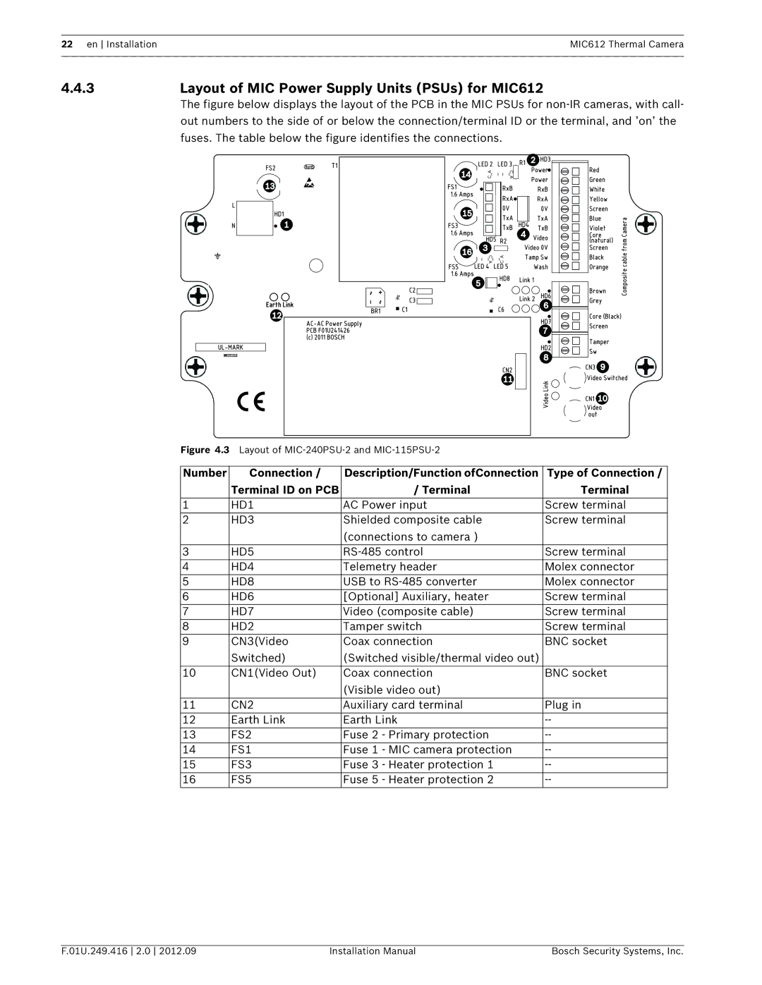
3Layout of MIC Power Supply Units PSUs for MIC612
4Installation Instructions
Electrical Shock Hazard
Number Description
PCB Marking Description
AUX1
Number Description Cable Gland Size
AUX2
MIC612 Thermal Camera Installation en
Commissioning the Camera with Heater Option Fitted
Power supply. Follow these steps
Disconnect the power supply from the power source
LED Description
Head is facing up
Fitting the Optional Sunshield MIC612
Bottom half of the sunshield see step
Screwdriver
Establishing Control of the Camera
Establishing Control of the Camera via Biphase Protocol
Getting Started
Establishing Control of the Camera via RS-485 Protocol
Basic Keyboard Operation
Powering On
Controlling the Camera
LCD
4Keyboard Commands, Pelco Protocol
Keyboard Commands, Bosch Protocol
Navigating the On-Screen Display OSD Menus
Special Preset Commands, Pelco Protocol
4Setting the Addresses of the Two Cameras of the MIC612
Preset
Setting the Address of the Optical Camera via FastAddress
FastAddress, Bosch Protocol
To change or clear an address for a camera with an address
3FastAddress, Pelco Protocols
To set an address for a camera without an address
To set FastAddress with a Pelco Keyboard
Active Commands in FastAddress
Setting Passwords
Configuring the Camera for Inverted Operation
Special Passwords
Setup Menu
6On-Screen Display OSD Menus Bosch Protocol
Camera Setup Menu
ATW
WDR
Thermal Camera Setup Menu
Lens Setup Menu
Manual
PTZ Setup Menu
Display Setup Menu
Azimuth
Display Adjust
Camera OSD
Compass
AutoBaud
Communication Setup Menu
Communication Setup
Baud Rate
Alarm Setup
None
Outputs
Outputs Setup Submenu
Outputs Setup Submenu Choices
OSD
Rule Setup Submenu Choices
Rule Setup Submenu
Rule Setup
Rule # Choices Enabled
Input
Language Menu
Output
Diagnostics Menu
Bist
Power Up Events
Security Access
Ctfid Access
Internal Humidity
Alarm Output
Alarm Status Submenu
Alarm Input
Total Time On
On-Screen Display OSD Menus Pelco Protocol
Bosch Menu
Camera Setup
Pelco menu Bosch menu Setup Menu
Continuous
Outdoor
PTZ Setup
White
Balance
Other Menus
OFF
Operation of the Thermal Camera
Switching Video
Displaying Thermal Camera Temperature
Flat-Field Correction FFC
Set the Temperature Threshold
Triggering Alarms On Detection of Objects Outside of Set
Thermal Temperature Threshold
Set the Alarm Rule
Setting Preset Shots
Common User Commands
Setting AutoPan Mode
Specifying a Shot or a Sector Title
Configuring Preposition Tours
Programming the Inactivity Operation
Using the Wiper/Washer
Recording Tours
10.1.1 Controlling Alarm Rules
Advanced Features
10.1 Alarm Rules
10.1.2 Alarm Rule Examples
Example 2 Advanced Alarm Rule
10.2 Privacy Masking
10.4 Pre-position Tour
10.5.1 Setting the Azimuth Zero Point
10.3 Image Stabilization
10.5 Azimuth, Elevation, and Compass Directions
10.5.2 Displaying Azimuth, Elevation, and Compass Headings
180 / -45 S
11Maintenance and Troubleshooting
Problem Explanation Solution
Keyboard Commands Bosch Protocol
Keyboard Commands By Number
Commands, Optical Camera
Zone/Sector Title Menu Enters the Zone Title menu. Refer to
Refer to .5 Azimuth, Elevation, Compass Directions,
Commands, Thermal Camera
70 en MIC612 Thermal Camera
Keyboard Commands Pelco Protocol
Keyboard User Action Description Command
En MIC612 Thermal Camera
#-ENTER
Index
Pre-compensation 39 sharpness 38 shutter White balance
En Index MIC612 Thermal Camera
Constant focus 41 manual focus 41 spot focus
Custom tour
PTZ
Shot
Zero pan
Page
Page
Bosch Security Systems, Inc