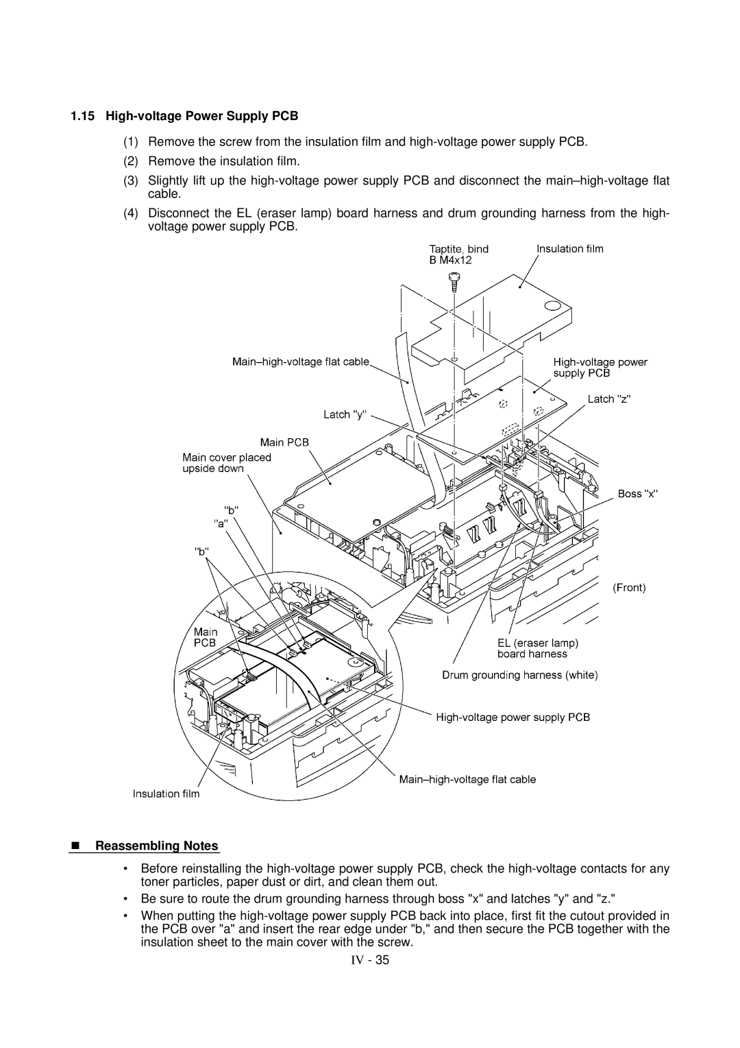
1.15High-voltage Power Supply PCB

(1)Remove the screw from the insulation film and high-voltage power supply PCB.

(2)Remove the insulation film.

(3)Slightly lift up the high-voltage power supply PCB and disconnect the main–high-voltage flat cable.

(4)Disconnect the EL (eraser lamp) board harness and drum grounding harness from the high- voltage power supply PCB.

nReassembling Notes

Before reinstalling the high-voltage power supply PCB, check the high-voltage contacts for any toner particles, paper dust or dirt, and clean them out.

Be sure to route the drum grounding harness through boss "x" and latches "y" and "z."

When putting the high-voltage power supply PCB back into place, first fit the cutout provided in the PCB over "a" and insert the rear edge under "b," and then secure the PCB together with the insulation sheet to the main cover with the screw.

IV - 35

Page 73
Image 73
Brother FAX-8650P service manual High-voltage Power Supply PCB