1.9Handset Mount and Hook Switch PCB (for the FAX3750/MFC7750) Side Cover (for the
(1)Open the top cover.
(2)Remove one of two screws from each of right and left top cover stoppers, then fully open the top cover.
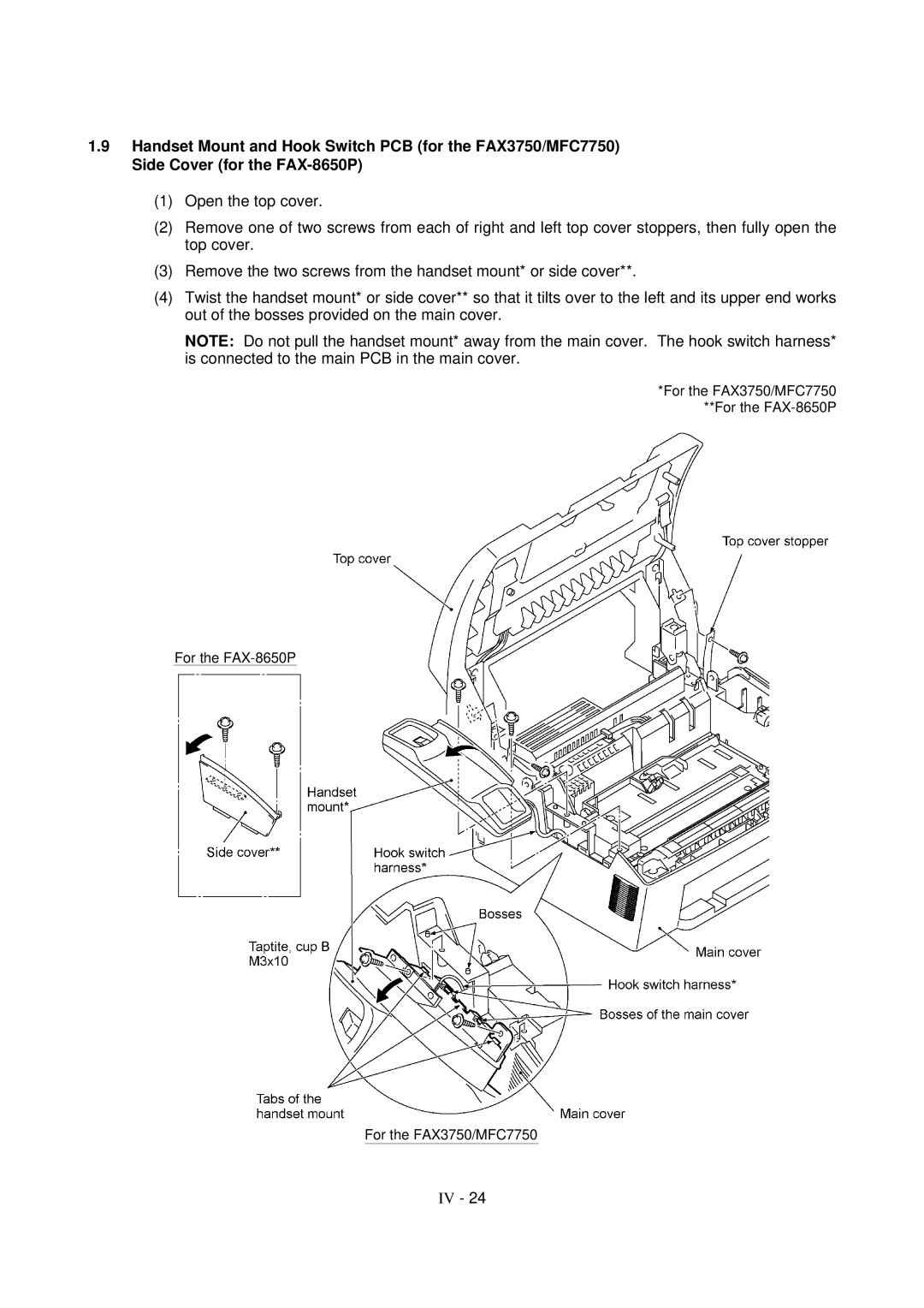
(3)Remove the two screws from the handset mount* or side cover**.
(4)Twist the handset mount* or side cover** so that it tilts over to the left and its upper end works out of the bosses provided on the main cover.
NOTE: Do not pull the handset mount* away from the main cover. The hook switch harness* is connected to the main PCB in the main cover.
*For the FAX3750/MFC7750 **For the FAX-8650P
For the
For the FAX3750/MFC7750
IV - 24