Chapter 2 Installing the Access Point
Connecting the Ethernet and Power Cables
Step 2 To mount your Cisco Aironet antenna, refer to the instructions that came with your antenna.
Connecting the Ethernet and Power Cables
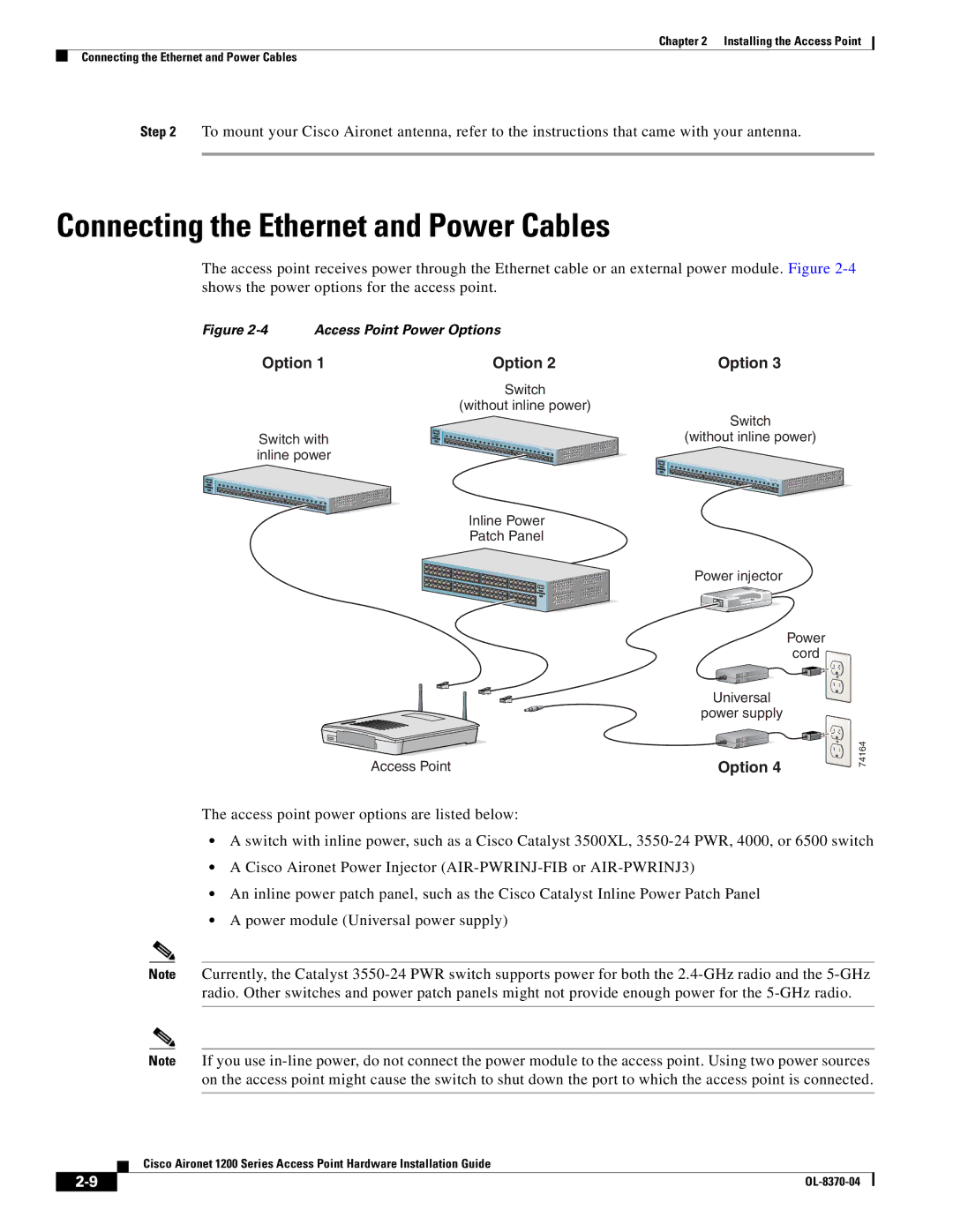
The access point receives power through the Ethernet cable or an external power module. Figure
Figure 2-4 Access Point Power Options
Option 1
Switch with inline power
Catalyst 2950
Option 2 | Option 3 |
Switch
(without inline power)
Switch
(without inline power)
Catalyst 2950
Catalyst 2950
Inline Power
Patch Panel
Power injector
Power cord ![]()
Universal
power supply
Access Point | Option 4 |
The access point power options are listed below:
74164
•A switch with inline power, such as a Cisco Catalyst 3500XL,
•A Cisco Aironet Power Injector
•An inline power patch panel, such as the Cisco Catalyst Inline Power Patch Panel
•A power module (Universal power supply)
Note Currently, the Catalyst
Note If you use
Cisco Aironet 1200 Series Access Point Hardware Installation Guide
| ||
|