Chapter 2 Installing the Access Point
Before Beginning the Installation
Before Beginning the Installation
Before you begin the installation process, please refer to Figure
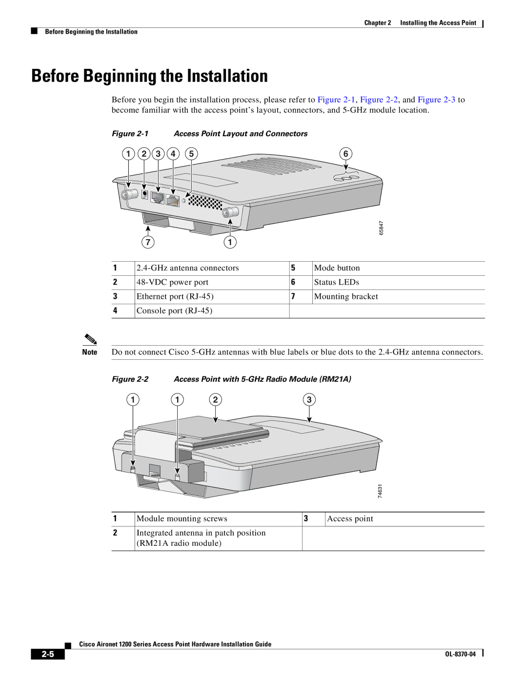
Figure 2-1 Access Point Layout and Connectors
1 | 2 | 3 | 4 | 5 | 6 |
|
|
|
| 65847 |
| 7 | 1 |
|
|
1 | 5 | Mode button | ||
2 |
| 6 | Status LEDs | |
3 | Ethernet port |
| 7 | Mounting bracket |
4 | Console port |
|
|
|
Note Do not connect Cisco
Figure 2-2 Access Point with 5-GHz Radio Module (RM21A)
1 | 1 | 2 | 3 |
74631
1 | Module mounting screws | 3 | Access point |
|
|
|
|
2 | Integrated antenna in patch position |
|
|
| (RM21A radio module) |
|
|
|
|
|
|
Cisco Aironet 1200 Series Access Point Hardware Installation Guide
| ||
|