Appendix B Cable and Connector Specifications
Console Port Cabling Specifications and Pinouts
2.Requires 5 dB 1550 nm fixed loss attenuator for < 20 km. Attenuator is available as a spare. The part number is
3.Links longer than 30 km are considered engineered links.
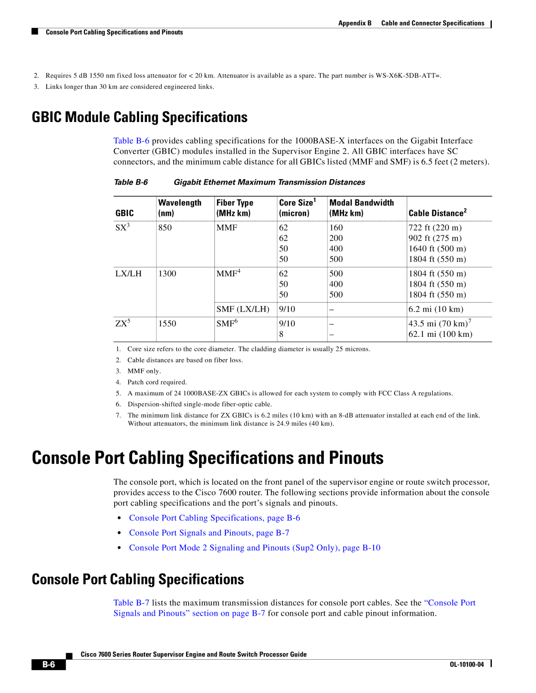
GBIC Module Cabling Specifications
Table
Table | Gigabit Ethernet Maximum Transmission Distances |
| |||
|
|
|
|
|
|
| Wavelength | Fiber Type | Core Size1 | Modal Bandwidth | Cable Distance2 |
GBIC | (nm) | (MHz km) | (micron) | (MHz km) | |
SX3 | 850 | MMF | 62 | 160 | 722 ft (220 m) |
|
|
| 62 | 200 | 902 ft (275 m) |
|
|
| 50 | 400 | 1640 ft (500 m) |
|
|
| 50 | 500 | 1804 ft (550 m) |
|
|
|
|
|
|
LX/LH | 1300 | MMF4 | 62 | 500 | 1804 ft (550 m) |
|
|
| 50 | 400 | 1804 ft (550 m) |
|
|
| 50 | 500 | 1804 ft (550 m) |
|
|
|
|
|
|
|
| SMF (LX/LH) | 9/10 | – | 6.2 mi (10 km) |
|
|
|
|
|
|
ZX5 | 1550 | SMF6 | 9/10 | – | 43.5 mi (70 km)7 |
|
|
| 8 | – | 62.1 mi (100 km) |
|
|
|
|
|
|
1.Core size refers to the core diameter. The cladding diameter is usually 25 microns.
2.Cable distances are based on fiber loss.
3.MMF only.
4.Patch cord required.
5.A maximum of 24
6.
7.The minimum link distance for ZX GBICs is 6.2 miles (10 km) with an
Console Port Cabling Specifications and Pinouts
The console port, which is located on the front panel of the supervisor engine or route switch processor, provides access to the Cisco 7600 router. The following sections provide information about the console port cabling specifications and the port’s signals and pinouts.
•Console Port Cabling Specifications, page
•Console Port Signals and Pinouts, page
•Console Port Mode 2 Signaling and Pinouts (Sup2 Only), page
Console Port Cabling Specifications
Table
Cisco 7600 Series Router Supervisor Engine and Route Switch Processor Guide
|
|
| |
|
|