Chapter 1 Cisco 7600 Product Overview
Cisco 7600 Series Routers
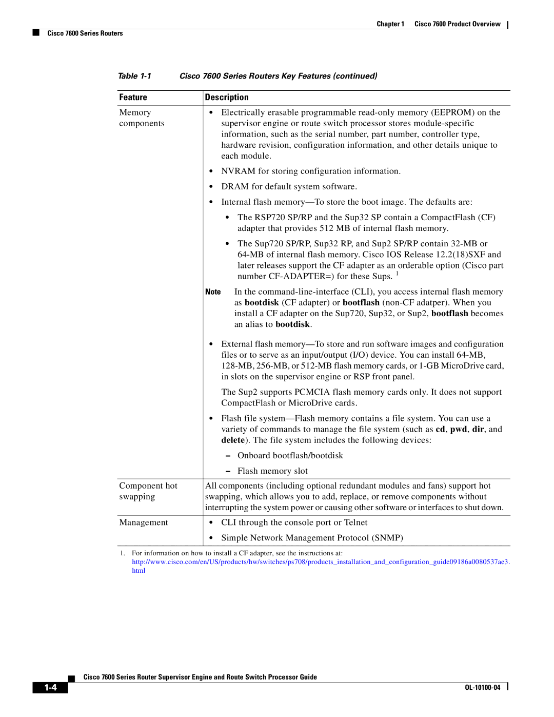
Table | Cisco 7600 Series Routers Key Features (continued) | |
|
| |
Feature | Description | |
|
| |
Memory | • Electrically erasable programmable | |
components | supervisor engine or route switch processor stores | |
| information, such as the serial number, part number, controller type, | |
| hardware revision, configuration information, and other details unique to | |
| each module. | |
| • NVRAM for storing configuration information. | |
| • DRAM for default system software. | |
| • Internal flash | |
| • The RSP720 SP/RP and the Sup32 SP contain a CompactFlash (CF) | |
|
| adapter that provides 512 MB of internal flash memory. |
| • The Sup720 SP/RP, Sup32 RP, and Sup2 SP/RP contain | |
|
| |
|
| later releases support the CF adapter as an orderable option (Cisco part |
|
| number |
| Note In the | |
|
| as bootdisk (CF adapter) or bootflash |
|
| install a CF adapter on the Sup720, Sup32, or Sup2, bootflash becomes |
|
| an alias to bootdisk. |
| • External flash | |
| files or to serve as an input/output (I/O) device. You can install | |
| ||
| in slots on the supervisor engine or RSP front panel. | |
| The Sup2 supports PCMCIA flash memory cards only. It does not support | |
| CompactFlash or MicroDrive cards. | |
| • Flash file | |
| variety of commands to manage the file system (such as cd, pwd, dir, and | |
| delete). The file system includes the following devices: | |
| – | Onboard bootflash/bootdisk |
| – | Flash memory slot |
|
| |
Component hot | All components (including optional redundant modules and fans) support hot | |
swapping | swapping, which allows you to add, replace, or remove components without | |
| interrupting the system power or causing other software or interfaces to shut down. | |
|
| |
Management | • CLI through the console port or Telnet | |
•Simple Network Management Protocol (SNMP)
1.For information on how to install a CF adapter, see the instructions at: http://www.cisco.com/en/US/products/hw/switches/ps708/products_installation_and_configuration_guide09186a0080537ae3. html
Cisco 7600 Series Router Supervisor Engine and Route Switch Processor Guide
|
| |
|