Chapter 2 Route Switch Processors and Supervisor Engines
Supervisor Engine 720 and Supervisor Engine 32
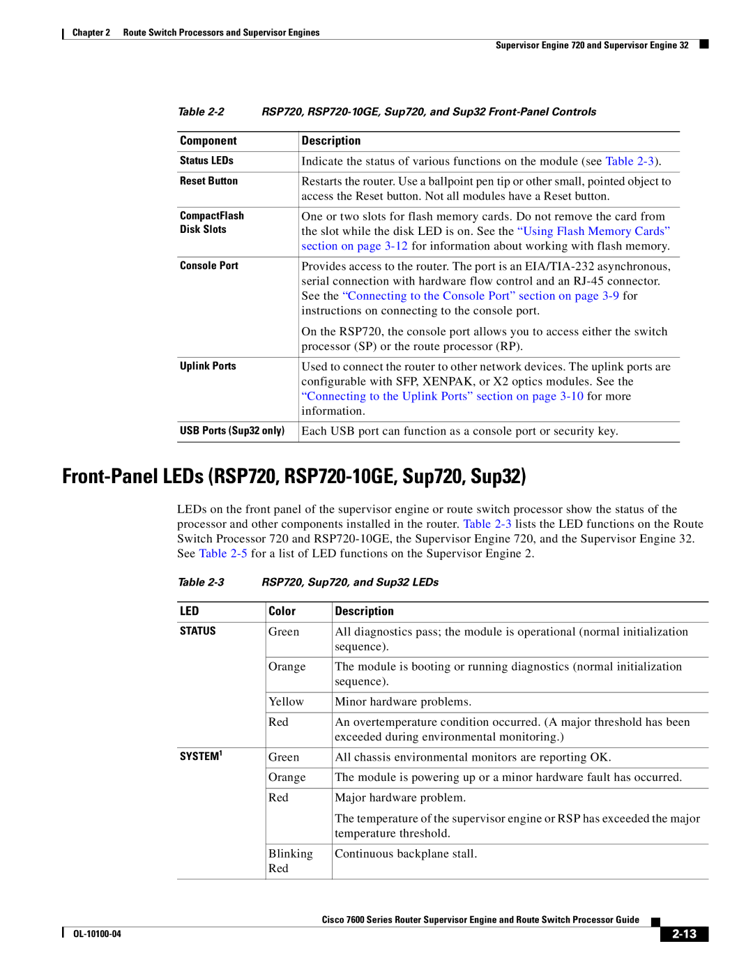
Table
Component | Description |
|
|
Status LEDs | Indicate the status of various functions on the module (see Table |
|
|
Reset Button | Restarts the router. Use a ballpoint pen tip or other small, pointed object to |
| access the Reset button. Not all modules have a Reset button. |
|
|
CompactFlash | One or two slots for flash memory cards. Do not remove the card from |
Disk Slots | the slot while the disk LED is on. See the “Using Flash Memory Cards” |
| section on page |
|
|
Console Port | Provides access to the router. The port is an |
| serial connection with hardware flow control and an |
| See the “Connecting to the Console Port” section on page |
| instructions on connecting to the console port. |
| On the RSP720, the console port allows you to access either the switch |
| processor (SP) or the route processor (RP). |
|
|
Uplink Ports | Used to connect the router to other network devices. The uplink ports are |
| configurable with SFP, XENPAK, or X2 optics modules. See the |
| “Connecting to the Uplink Ports” section on page |
| information. |
|
|
USB Ports (Sup32 only) | Each USB port can function as a console port or security key. |
|
|
Front-Panel LEDs (RSP720, RSP720-10GE, Sup720, Sup32)
LEDs on the front panel of the supervisor engine or route switch processor show the status of the processor and other components installed in the router. Table
|
| Table | RSP720, Sup720, and Sup32 LEDs | ||||||
|
|
|
|
|
|
| |||
|
| LED |
| Color |
| Description | |||
|
|
|
|
|
|
| |||
|
| STATUS |
| Green |
| All diagnostics pass; the module is operational (normal initialization | |||
|
|
|
|
|
| sequence). | |||
|
|
|
|
|
|
| |||
|
|
|
| Orange |
| The module is booting or running diagnostics (normal initialization | |||
|
|
|
|
|
| sequence). | |||
|
|
|
|
|
|
| |||
|
|
|
| Yellow |
| Minor hardware problems. | |||
|
|
|
|
|
|
| |||
|
|
|
| Red |
| An overtemperature condition occurred. (A major threshold has been | |||
|
|
|
|
|
| exceeded during environmental monitoring.) | |||
|
|
|
|
|
|
| |||
|
| SYSTEM1 |
| Green |
| All chassis environmental monitors are reporting OK. | |||
|
|
|
|
|
|
| |||
|
|
|
| Orange |
| The module is powering up or a minor hardware fault has occurred. | |||
|
|
|
|
|
|
| |||
|
|
|
| Red |
| Major hardware problem. | |||
|
|
|
|
|
| The temperature of the supervisor engine or RSP has exceeded the major | |||
|
|
|
|
|
| temperature threshold. | |||
|
|
|
|
|
|
| |||
|
|
|
| Blinking |
| Continuous backplane stall. | |||
|
|
|
| Red |
|
|
|
|
|
|
|
|
|
|
|
|
|
| |
|
|
|
|
| Cisco 7600 Series Router Supervisor Engine and Route Switch Processor Guide |
|
| ||
|
|
|
|
|
| ||||
|
|
|
|
|
|
|
|
|
|
|
|
|
|
|
|
| |||
|
|
|
|
|
|
| |||