Appendix B Cable and Connector Specifications
Console Port Mode 2 Signaling and Pinouts (Sup2 Only)
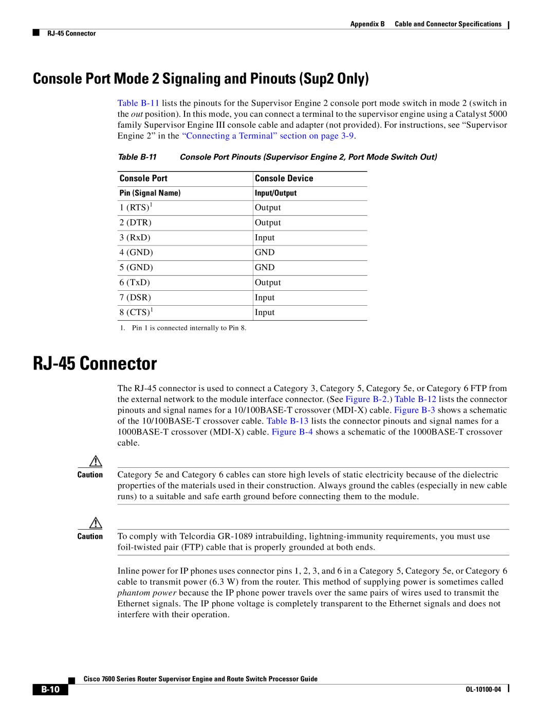
Table
Table
Console Port | Console Device | |
|
| |
Pin (Signal Name) | Input/Output | |
|
|
|
1 | (RTS)1 | Output |
2 | (DTR) | Output |
|
|
|
3 | (RxD) | Input |
|
|
|
4 | (GND) | GND |
|
|
|
5 | (GND) | GND |
|
|
|
6 | (TxD) | Output |
|
|
|
7 | (DSR) | Input |
|
|
|
8 | (CTS)1 | Input |
1. Pin 1 is connected internally to Pin 8.
RJ-45 Connector
The
Caution Category 5e and Category 6 cables can store high levels of static electricity because of the dielectric properties of the materials used in their construction. Always ground the cables (especially in new cable runs) to a suitable and safe earth ground before connecting them to the module.
Caution To comply with Telcordia
Inline power for IP phones uses connector pins 1, 2, 3, and 6 in a Category 5, Category 5e, or Category 6 cable to transmit power (6.3 W) from the router. This method of supplying power is sometimes called phantom power because the IP phone power travels over the same pairs of wires used to transmit the Ethernet signals. The IP phone voltage is completely transparent to the Ethernet signals and does not interfere with their operation.
| Cisco 7600 Series Router Supervisor Engine and Route Switch Processor Guide |