Chapter 3 Installing and Configuring Route Switch Processors and Supervisor Engines
Connecting to the Uplink Ports
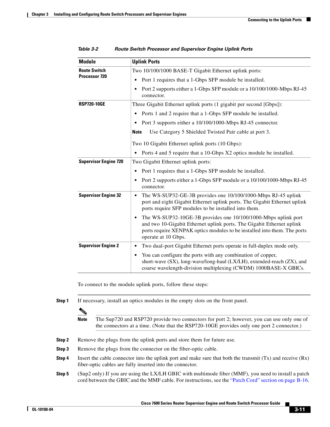
Table
Module | Uplink Ports |
|
|
Route Switch | Two 10/100/1000 |
Processor 720 | • Port 1 requires that a |
| |
| • Port 2 supports either a |
| connector. |
|
|
Three Gigabit Ethernet uplink ports (1 gigabit per second [Gbps]): | |
| • Ports 1 and 2 require that a |
| • Port 3 supports either a |
| Note Use Category 5 Shielded Twisted Pair cable at port 3. |
| Two 10 Gigabit Ethernet uplink ports (10 Gbps): |
| • Ports 4 and 5 require that a |
|
|
Supervisor Engine 720 | Two Gigabit Ethernet uplink ports: |
| • Port 1 requires that a |
| • Port 2 supports either a |
| connector. |
|
|
Supervisor Engine 32 | • The |
| port and eight Gigabit Ethernet uplink ports. The Gigabit Ethernet uplink |
| ports require SFP modules to be installed into them. |
| • The |
| and two |
| ports require XENPAK optics modules to be installed into them. The ports |
| operate at 10 Gbps. |
|
|
Supervisor Engine 2 | • Two |
| • You can configure the ports with any combination of copper, |
| |
| coarse |
|
|
To connect to the module uplink ports, follow these steps:
Step 1 If necessary, install an optics modules in the empty slots on the front panel.
Note The Sup720 and RSP720 provide two connectors for port 2; however, you can use only one of the connectors at a time. (Note that the
Step 2 Remove the plugs from the uplink ports and store them for future use.
Step 3 Remove the plugs from the connector on the
Step 4 Insert the cable connector into the uplink port and make sure that both the transmit (Tx) and receive (Rx)
Step 5 (Sup2 only) If you are using the LX/LH GBIC with multimode fiber (MMF), you need to install a patch cord between the GBIC and the MMF cable. For instructions, see the “Patch Cord” section on page
|
| Cisco 7600 Series Router Supervisor Engine and Route Switch Processor Guide |
|
| |
|
|
| |||
|
|
|
| ||
|
|
|
| ||