Text Part Number OL-3141-01
Corporate Headquarters
Copyright 2003, Cisco Systems, Inc All rights reserved
Iii
N T E N T S
What You Need
DNS1IP DNS2IP
Recommended Values
Vii
Syntax
Viii
Cisco ATA Style Conference Calling Procedure A-7
Overview
Preface
Audience
Organization
Conventions
Preface Conventions
Related Documentation
Cisco IOS Telephony Service documentation
Obtaining Documentation
Cisco.com
Documentation CD-ROM
International Cisco web sites can be accessed from this URL
Ordering Documentation
Documentation Feedback
Technical Assistance Center
Obtaining Technical Assistance
Cisco TAC Website
Xiv
Cisco TAC Escalation Center
Obtaining Additional Publications and Information
Xvi
A P T E R
Cisco Analog Telephone Adaptor Overview
4illustrates the architecture of an Sccp network
Overview of the Skinny Client Control Protocol
Link LED
Hardware Overview
Function Button
Sccp Version
Software Features
Voice Codecs Supported
Basic Services
Additional Supported Signaling Protocols
Other Supported Protocols
Pre-call and Mid-call Services
Fax Services
Pre-call Services
Pre-call Services, Mid-call Services,
Style and Related Services Procedure Reference
Mid-call Services
Cisco ATA style services Cisco ATA Style, page A-6
Bellcore Style, page A-4
Action Reference
Installation and Configuration Overview
OL-3141-01
Installing the Cisco ATA
Network Requirements
Safety Recommendations
What the Cisco ATA Package Includes
5V power adaptor Power cord
Installation Procedure
What You Need
Cisco ATA 186 Rear Panel Connections
Procedure
Installing the Cisco ATA Installation Procedure
Power-Down Procedure
Configuring the Cisco ATA for Sccp
Default Boot Load Behavior
Page
Feature
VLANSetting
Parameter and Bits Reference
Bits
Hexadecimal format, this value is 0x01cc002b
Action Reference
Steps Needed to Configure the Cisco ATA
Basic Configuration Steps in a Non-TFTP Server Environment
Configuring the Cisco ATA Using a Tftp Server
Action
Configurable Features and Related Parameters
Setting Up the Tftp Server with Cisco ATA Software
Configurable Features Related Parameters
Parameters Not Used for Sccp
Creating a Cisco ATA Default Configuration File
Syntax
Syntax of the cfgfmt program follows
You could change the values as follows
Creating a Configuration File for a Specific Cisco ATA
Save your changes
Cfgfmt -tmgcpptag.dat ata0a141e28323c.txt ata0a141e28323c
Using atapname.exe Tool to Obtain MAC Address
Command Example
Using the EncryptKey Parameter and cfgfmt Tool
Command Output
Syntax examples
Using a Dhcp Server,
Using a Dhcp Server
Without Using a Dhcp Server,
Procedure
Other Dhcp Options You Can Set
Without Using a Dhcp Server
Using the Voice Configuration Menu
Voice Configuration Menu
Voice Menu Number Features
Entering Alphanumeric Values
Resetting the Cisco ATA to Factory Default Values
Key Alphanumeric Characters
Cisco ATA Web Configuration
DNS1IP
Resetting the Cisco ATA Using Cisco CallManager
Confirmation box appears. Click OK
Upgrading the Sccp Signaling Image
Adding the Cisco ATA to the Cisco CallManager
Adding Cisco ATAs Manually
Default value of None
Time
Click OK
Using the Cisco Bulk Administration Tool BAT
Using Auto-Registration
Parameters and Defaults
CA0UID0 CA1UID0
Configuration Text File Template
User Interface UI Parameter
UIPassword
Settings
Parameters for Configuration Method and Encryption
Range Default Voice Configuration Menu Access Code
UseTFTP
Maximum 31 characters
EncryptKey
905
UseTFTP, Domain,
320
Network Parameters
UseTFTP, TftpURL,
DHCP, StaticIp, StaticRoute, StaticNetMask,
StaticIp
Voice Configuration Menu Access Code Related Parameters
StaticRoute
DHCP, StaticRoute, StaticNetMask,
StaticNetMask
Account Information Parameters
EPID0orSID0 and EPID1orSID1
Value Types
CA0orCM0 and CA1orCM1
Voice Configuration Menu Access Codes
Examples
Operating Parameters
Sccp Mode Parameter
UseMGCP
Other Parameters
Integer
LBRCodec
AudioMode
PrfCodec
ConnectMode, page 5-13bit AudioMode, page 5-12bits 1
LBRCodec, ConnectMode,
Bit Number Definition
ConnectMode
0x90000400
311
CallerIdMethod
To Use Pre-call and Mid-call Services
316
0x00019e60
916
DHCP,
917
Domain
OpFlags
NumTxFrames
TftpURL, CA0orCM0 and CA1orCM1,
TftpURL, DHCP, VLANSetting,
VLANSetting
See the VLANSetting section on
SigTimer
Optional Feature Parameters
CallWaitTone,
RingCadence
Default Recommended Values
List of Call-Progress Tone Parameters
Call-Progress Tone Parameters
Tone Parameter Syntax
Each tone is specified by nine integers, as follows
Recommended Values
How to Calculate Scaling Factors
Use the following formula to calculate the scaling factor a
Specific Call-Progress Tone Parameter Information
Default values for the nine-integer array
DialTone
920
BusyTone
Cisco ATA plays the busy tone when the callee is busy
ReorderTone
921
CallWaitTone
RingbackTone
923
924
ConfirmTone
NPrintf
925
Extended IP address
UDPTOS, VLANSetting,
Range Default
TraceFlags
MediaPort
Page
Using Fax Pass-through Mode
Configuring and Debugging Fax Services
This setting translates to the following bitmap
Configuring the Cisco ATA for Fax Pass-through mode
AudioMode
AudioMode, ConnectMode,
Recommended Setting
Configuring Cisco IOS Gateways to Enable Fax Pass-through
This setting translates to the bitmap
Enable Fax Pass-through Mode, Disable Fax Relay Feature,
System Level commands
Enable Fax Pass-through Mode
Run the following command
Dial-Peer Level Commands
Disable Fax Relay Feature
Perform the command
Configuring the Cisco ATA for Fax Mode
Using FAX Mode
Configuring the Cisco IOS Gateway for Fax Mode
Debugging the Cisco ATA 186/188 Fax Services
Common Problems When Using IOS Gateways
Run the command
Prserv Overview
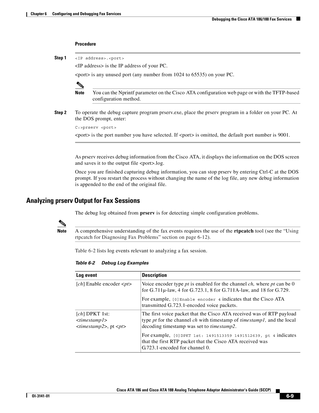
Using prserv for Diagnosing Fax Problems
Prserv Overview, Analyzing prserv Output for Fax Sessions,
Log event Description
Analyzing prserv Output for Fax Sessions
Decoding timestamp was set to timestamp2
That the first RTP packet that the Cisco ATA received was
100
Debugging FAX Pass-through Mode
Terminating-Gateway Example
Originating-Gateway Example
Debugging FAX Mode
Possible Reasons for Failure
How to Use
Using rtpcatch for Diagnosing Fax Problems
Rtpcatch Overview
Major functions
Options
Example of rtpcatch
Output
CED tone Detected
Explanation
1032.116=2.213
Analyzing rtpcatch Output for Fax Sessions
Fax relay mode Cisco fax relay mode
Analysis
Both sides use G.711 for the entire fax session
Possible Causes for Failure
Using rtpcatch to Analyze Common Causes of Failure
Possible Cause for Failure
Cisco fax relay option is not disabled on the gateway
Rtpcatch Limitations
Example 6-10 Fax Pass-through Mode Failure
Page
Upgrading the Cisco ATA Signaling Image
Procedure for Upgrading all Cisco ATAs at Once
Upgrading the Signaling Image Via Cisco CallManager
Upgradecode Syntax
ProcedureforUpgradingOneCiscoATA
Upgradecode Definitions
Running the Executable
Preliminary Steps
Upgrading the Signaling Image Manually
Running the Executable File
Preliminary Steps, Running the Executable File,
Upgrade Procedure
Upgrade Requirements
Syntax
Definitions
Using a Web Browser
Confirming a Successful Signaling Image Upgrade
Using the telephone keypad, enter the following
Using a Web Browser, Using the Voice Configuration Menu,
Using the Voice Configuration Menu
OL-3141-01
General Troubleshooting Tips
Troubleshooting
Symptoms and Actions
Installation and Upgrade Issues
Restarting the Cisco CallManager
Debugging
You should also have access to a sniffer or LAN analyzer
Ring Load per RJ-11 FXS Port Maximum Distance
Frequently Asked Questions
Procedure
Contacting TAC
Procedures for Using Pre-call Services
How to Use Pre-call and Mid-call Services
Access Voicemail
Activate Call-Forward-All
Cancel Call-Forward-All
Redial
Speed Dial
Call Pickup
To use this feature, follow these steps
Group Call Pickup
MeetMe Conference
Bellcore Style Call Transfer Procedure
Procedures for Using Mid-call Services
Bellcore Style Conference Call Procedure
Bellcore Style
Cisco VG248 Call Transfer Procedure
Cisco VG248 Style Three-way Calling Procedure
Cisco VG248 Style
Cisco ATA Style Call Hold/Resume Procedure
Cisco VG248 Conference Call Procedure
Cisco ATA Style Call Transfer Procedure
Cisco ATA Style
Cisco ATA Style Conference Calling Procedure
OL-3141-01
Table B-1lists codes to return basic Cisco ATA information
Voice Menu Codes
Voice Menu Option Code Description
DNS 2 IP
916 IP address of the primary DNS server
Table B-3 Cisco ATA Voice Menu Codes-Software Upgrade
OL-3141-01
Physical Specifications
Cisco ATA Specifications
Specification
Environmental Specifications
Electrical Specifications for Cisco ATA
Immunity Specifications
Description Specification
Software Specifications
Ringing Characteristics
Physical Interfaces
Tip/ring interfaces for each RJ-11 FXS port Slic
Appendix C Cisco ATA Specifications Software Specifications
Sccp
OL-3141-01
Supported Sccp Message Set
Sccp Call Flows
This section describes basic call flows for the Cisco ATA
Appendix D Sccp Call Flows Supported Sccp Message Set
Cisco ATA-to-Cisco CallManager
Call Flow Scenarios for Successful Calls
ATA
Step Action Description
Step Station Call Info Description
Cisco ATA-to-Cisco CallManager-to-Cisco ATA
Step Station Call Info Description
Step Station Call Info Description
OL-3141-01
Syntax of upgradecode Parameter
Performing a Cross-Protocol Upgrade
Process
Upgradecode parameter value could be
GL-1
GL-2
GL-3
GL-4
Messages can be part of Sgcp and Mgcp messages
Signaling connection control part
GL-5
GL-6
Traffic
Business-class services for Internet telephony
Allow you to define your own customized markup language
GL-7
GL-8
IN-1
EncryptKey
CallerIdMethod ConnectMode Dhcp
Enabling use
IN-2
IN-3
IN-4
RTP frames RTP media port configuration
IN-5
Safety recommendations Scaling factor calculation
IN-6
IP encapsulation