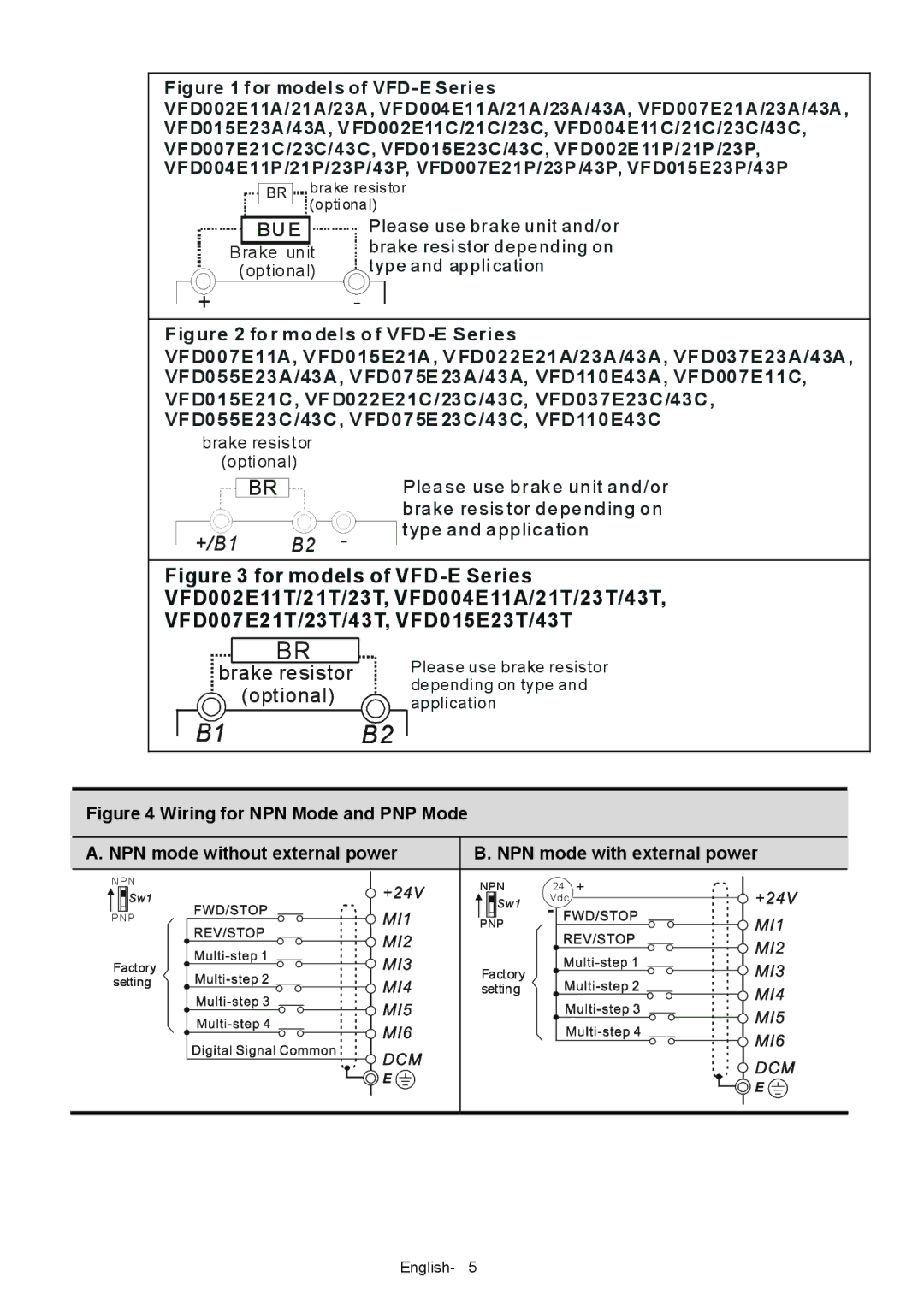
Figure 1 for models of VFD- E Series
VFD002E11A/21A/23A, VFD004E11A/21A/23A/43A, VFD007E21A/23A/43A, VFD015E23A/43A, V FD002E11C/21C/23C, VFD004E11C/21C/23C/43C, VFD007E21C/23C/43C, VFD015E23C/43C, VFD002E 11P/21P /23P, VFD004E11P /21P/23P/43P, VFD007E21P/23P /43P, VFD015E23P/43P
| brake resistor | |
BR | ||
(opti onal) | ||
|
BUE
Brake unit (optional)
Please use brake unit and/or brake resi stor depending on type and appli cati on
+-
Figure 2 for models of VFD-E Series
VFD007E11A, V FD015E21A, V FD022E21A/23A/43A, VFD037E23A/43A, VFD055E23A/43A, V FD075E 23A/43A, VFD110E43A, VFD007E11C, VFD015E21C, VFD022E21C/23C/43C, VFD037E23C/43C, VFD055E23C/43C, V FD075E 23C/43C, VFD110E43C
brake resistor (opti onal)
BR
+/B1 | B2 - |
Please use brak e unit and/or brake resis tor depending on type and applic ation
Figure 3 for models of VFD-E Series VFD002E11T/21T/23T, VFD004E11A/21T/23T/43T, VFD007E21T/23T/43T, VFD015E23T/43T
BR
brake resistor  (optional)
Please use brake resistor depending on type and application
B2
Figure 4 Wiring for NPN Mode and PNP Mode
A. NPN mode without external power | B. NPN mode with external power | ||
NPN | NPN | 24 | + |
| |||
|
| Vdc |
|
PNP | PNP | - |
|
|
|
| |
Factory | Factory |
|
|
setting |
|
| |
setting |
|
| |
|
|
| |
English- 5