GENERAL INFORMATION
LOCK
UNLOCK
1.11.4 REMOVING RF UNIT
1.Remove the five screws attaching the shield to the PC board.
2.Remove the two screws securing the RF power module to the chassis. Then remove the four stand- offs attaching the RF board to the chassis.
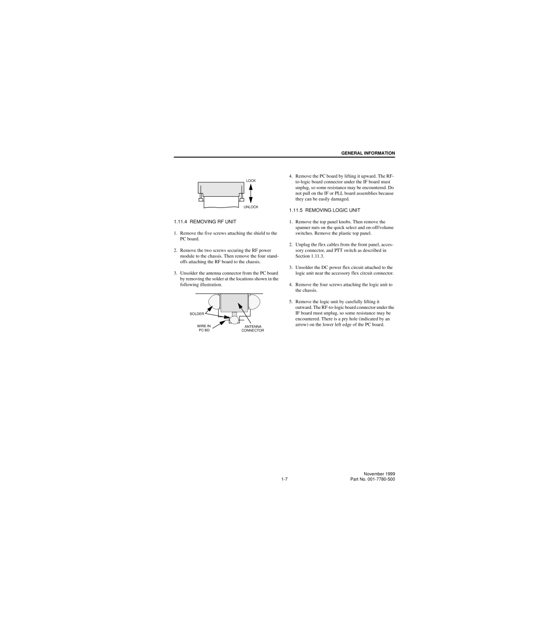
3.Unsolder the antenna connector from the PC board by removing the solder at the locations shown in the following illustration.
SOLDER |
WIRE IN | ANTENNA |
PC BD | CONNECTOR |
4.Remove the PC board by lifting it upward. The RF-
1.11.5 REMOVING LOGIC UNIT
1.Remove the top panel knobs. Then remove the spanner nuts on the quick select and
2.Unplug the flex cables from the front panel, acces- sory connector, and PTT switch as described in Section 1.11.3.
3.Unsolder the DC power flex circuit attached to the logic unit near the accessory flex circuit connector.
4.Remove the four screws attaching the logic unit to the chassis.
5.Remove the logic unit by carefully lifting it outward. The
| November 1999 |
Part No. |