TRANSCEIVER PROGRAMMING
Windows 95/98 - Select Start > Settings > Control Panel and double click “Add/Remove Programs”. Then click Install and Next. When SETUP.EXE is automatically located on the floppy drive, click Next, select the location for the
4. Follow the instructions displayed by the setup |
program. The default directory for the program is |
|
|
|
|
|
|
|
| PROGRAMMING CABLE |
|
|
|
|
|
|
|
| Part No. |
|
|
|
|
| 4 |
| RxD | Orange |
|
| To Radio | 6 |
| Gnd | Black | ||
|
| |||||||
| Accessory |
| ||||||
|
|
|
| |||||
| Connector | 2 |
| Mic Audio | Red | |||
|
| |||||||
|
|
|
|
|
| |||
|
|
|
|
|
| Reset [1] | Green | |
9 |
|
|
|
| 8 |
| ||
|
|
|
|
| ||||
|
|
|
|
| ||||
|
|
| 8 | 1 |
| PTT/Flash | Yellow | |
7 |
|
|
|
| ||||
|
| |||||||
|
|
| 6 | 5 |
| Vcc | Blue | |
5 |
|
|
|
| ||||
|
|
| 4 |
| ||||
|
|
|
|
|
| |||
3 |
|
|
| 9 |
| Speaker | White | |
2 |
| |||||||
1 |
| TxD | Brown | |||||
|
|
|
| 3 |
| |||
|
|
|
|
| ||||
|
|
|
|
|
| |||
|
|
|
|
|
|
|
| |
Modular
Connector
A ![]()
1
2
3 ![]() To
To
RPI
4
5
6
B ![]()
\Program Files\PCTrunk. If you wish to use some |
other directory, click Browse and select it or type the |
name. |
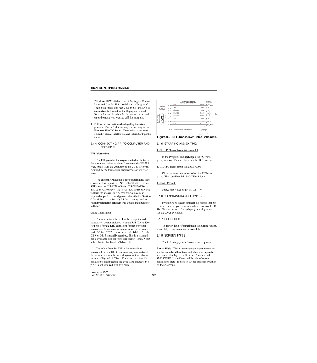
3.1.4CONNECTING RPI TO COMPUTER AND TRANSCEIVER
RPI Information
The RPI provides the required interface between the computer and transceiver. It converts the
The current RPI available for programming trans- ceivers of this type is Part No.
6.In addition, it is the only RPI that can be used to
Flash program the transceiver to update the operating software.
Cable Information
The cables from the RPI to the computer and transceiver are not included with the RPI. The
The cable from the RPI to the transceiver connects from the RPI to the accessory connector of the transceiver. A schematic diagram of this cable is shown in Figure
[1] Pin 8 is connected on
Pin A | Pin B |
Figure 3-2 RPI -Transceiver Cable Schematic
3.1.5 STARTING AND EXITING
To Start PCTrunk From Windows 3.1
In the Program Manager, open the PCTrunk group window. Then
To Start PCTrunk From Windows 95/98
Click the Start button and select the PCTrunk group. Then
To Exit PCTrunk:
Select File > Exit or press ALT + F4.
3.1.6 PROGRAMMING FILE TYPES
Programming data is stored in a disk file that can be saved, read, copied, and deleted (see Section 3.3.1). The file that is stored for each programming session has the .DAT extension.
3.1.7 HELP FILES
To display help information on the current screen, click Help in the menu bar or press F1.
3.1.8 SCREEN TYPES
The following types of screens are displayed:
November 1999 |
|
Part No. |