Manuals
/
EFJohnson
/
Communications
/
Two-Way Radio
EFJohnson
7780
service manual
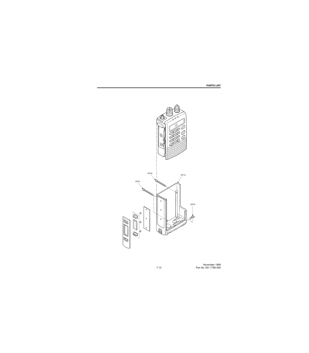
MP35 MP18 MP25
Models:
7780
1
97
116
116
Download
116 pages
9.93 Kb
94
95
96
97
98
99
100
101
Page 97
Image 97
PARTS LIST
F1
F2
CLR
F3
ENT
MP35
MP18
MP35
MP25
FCN
November 1999
7-13
Part No.
001-7780-500
Page 96
Page 98
Page 97
Image 97
Page 96
Page 98
Contents
7780
Page
Page
Table of Contents
Table of Contents CONT’D
List of Figures
List of Tables
Scope of Manual Equipment Description
General Information
Factory Customer Service
Accessories
Part Number Breakdown
Transceiver Identification
Accessory
Accessories
Toll-Free 800
Factory Returns
Internet Home Intrinsically Safe Information
Replacement Parts
Definitions
Possible Ignition Sources
Temperature Code T3C
Intrinsically Safe and Nonincendive Ratings
Classification of Hazardous Areas and Atmospheres
Material Classification
Accessing PC Boards
Typical Hazard Group Class
Area Classification
Removing Logic Unit
Removing RF Unit
General
Specifications
Transceiver Operation
Features
Controls and Display
Low-Battery Indicator Amber
TX Indicator Red Indicates when the transmitter is keyed
Front Panel Keys Full Keypad Model
Display
Display
Option Switches
Turning Power on and Setting Volume
General Operation
Backlight
Function Conv
Option Switch Functions
See
Scanning
Tone ENABLE/DISABLE
Conventional and SMARTNET/ Smartzone Operation
Display Mode Selection
Conventional Features
Monitoring Before Transmitting
Busy Channel Lockout
Monitor Mode
Call Guard Squelch
Conversation Timer
Penalty Timer
Power Output Select
Conventional Mode Scanning
Priority Channel Sampling
Standard Conventional Calls
DTMF/ANI Signaling
Viewing Unit ID
SMARTNET/SMARTZONE Features
Standard Group Calls
Enhanced Private Conversation Calls
Transceiver Operation
Private Conversation II Calls
Telephone Calls
Call Alert
Messaging
Emergency Alarm and Call
Sending Status Conditions
SMARTNET/SMARTZONE Scanning
Failsoft Operation
Dynamic Regrouping
Supervisory Tones
Menu Description
Keypad Programming
Zone Change Parameter
System Parameters
Channel Change Parameter
Channel Parameters
Pctrunk Software Installation
Programming Setup
Transceiver Programming
Computer Description
Starting and Exiting
Connecting RPI to Computer and Transceiver
Programming File Types
Help Files
Programming Procedure
Screen Pop-Up Buttons and File Size Indicator
File Size Indication
Creating and Displaying Systems
Menu Bar
Menu Commands
Download Menu Upload Menu
Radio Type Menu
Systems Menu
Window Menu
RADIO-WIDE Parameter Screens
Defaults
Band
Zones
Radio-Wide Scan List Screen
Radio Wide Scan List
Modify List Screen
Assign Function Buttons
RADIO-WIDE SMARTNET/SMARTZONE Screen
RADIO-WIDE Conventional Screen
Full Spectrum CC Scan
Hot Dtmf
RADIO-WIDE Portable Options Screen
Adjustable Parameters
Programming Conventional Systems and Channels
Conventional System General Screen
Conventional System Modify Scan List Screen
Timers
Keypad Editing
Scan List Button
Setting UP Conventional Channels
Scan Timers
Priority Channel Selection
Selected Channel
Conventional Channel Screen Parameters
Signaling
Transmit Power
Channel Type
Tx Time-Out
Time-Out Timer
Restricted Access
ISW Delay Time
Splinter Channels
SMARTNET/SMARTZONE System Phone Interconnect Screen
SMARTNET/SMARTZONE System Other ID’S Screen
Phone Interconnect
Private Call
Emergency Alarm
SMARTNET/SMARTZONE System Emergency Settings Screen
SMARTNET/SMARTZONE System Talk Groups Screen
Failsoft Channel
Trunking Phone List Screen
SMARTNET/SMARTZONE System Lists Screens
Message Aliasing Screen
Control Channels Screen
Announcement Groups Screen
Trunking Call List Screen
Status Aliasing Screen
Setting UP SMARTNET/SMART- Zone Channels
SMARTNET/SMARTZONE Channel Screen Parameters
Other Screen Parameters
SMARTNET/SmartZone Channel Screen
Recommended Tone Call Guard Codes Freq
Call Guard CTCSS/DCS Codes and Tones
MHz Channels
MHz Channels
MHz Channels
MHz Channels
MHz Channels
MHz Channels
Power Switching
Power Switching and Regulation
Circuit Description
Synthesizer Description
Synthesizer Chip IC1
VCO and Tcxo Modulation
Charge Pump Q1, Q2, Loop Filter
RF Amplifier Q1, First Mixer Q2
Receiver Circuit Description
If Amplifier Q2, LIMITER/DETECTOR IC3
Squelch Circuit IC4A/B, IC5A
Antenna Switch and LOW-PASS Filter
Transmitter Description
Amplifier Q9, Driver Q8
Receive Audio Processing
Control Logic and Display
Pin Port Name Input or Description Active High Output
Microprocessor IC306 Pin Descriptions
Hvfulswlrq
Receive and Transmit Data Processing
Audio Amplifier IC104-IC106
Receive Data FILTER/DETECTOR IC102A/B, IC107A/B
Transmit Audio Processing
Transmit Data Filter IC206B/ IC206A
Smartnet Data Processing
LOW-PASS Filter IC205A/B
Battery Pack
Battery Pack and Charger Information
Power Setting Operating Time
Function Fahrenheit Celsius
Battery Pack and Charger Information
Test Setup
Alignment Procedure and Performance Tests
Mm/3/32 Mm/1/8 Phone Jack
Tune Software Hqhudo
Main Pctune Screen
Preliminary Setup
Transmit Power Adjustment Screen
Transmit Frequency and Power
High Power Level = 3.0 watts Low Power Level = 1.0 watt
Modulation Balance
Rssi Adjust
Squelch Adjust
Audio Deviation
Data Deviation
Receiver Performance Tests
Performance Tests
Transmitter Performance Tests
Power Output
Transmit Frequency
Transmit Modulation
This page intentionally left blank
Display Assembly
Parts List
Chassis Parts
Ref No Description
Display Assembly
KEY Assembly
KEY Assembly
If Assembly
If Assembly
RF Unit
PLL Assembly
RF Unit
NJM2904V-TE1 IC
RF Unit
Logic Unit
Logic Unit
TDA7233D IC
Logic Unit
200K ERJ3GE
MP35 MP18 MP25
EP2
KEY Front Panel
EP1
MP32 MP33 MP27 MP34 MP28 MP29 MP23 MP22 MP30 MP24 MP26 MP18
PLL Board TOP View
Schematic Diagrams and Component Layouts
PLL Board Bottom View
If Board Bottom View
If Board TOP View
RF Unit
Transceiver Block Diagram
MIC
RF Board TOP View
If AMP
RF Board Schematic
HD1
Logic Board TOP View
Receive Audio Processing
Logic Board Schematic
GND KEYR3 KEYR2 KEYR1 KEYR0 KEYS3 KEYS2 KEYS1 KEYS0 GND
Display Board Bottom View
DS3 DS4 DS5
Display Board Schematic
KEY Board Back View
KEY Board Front View
S S R R R R
KEY Board Schematic
Scan
HC2 HC7 HC8 HC3
Schematic Diagrams and Component Layouts
Top
Page
Image
Contents