CIRCUIT DESCRIPTION
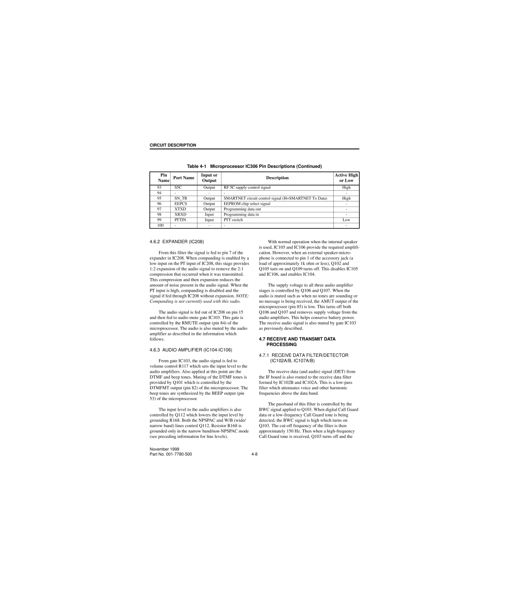
Table 4-1 Microprocessor IC306 Pin Descriptions (Continued)
Pin | Port Name | Input or | Description | Active High | |
Name | Output | or Low | |||
|
| ||||
|
|
|
|
| |
93 | S5C | Output | RF 5C supply control signal | High | |
94 | - | - | - | - | |
|
|
|
|
| |
95 | SN_TR | Output | SMARTNET circuit control signal (H=SMARTNET Tx Data) | High | |
|
|
|
|
| |
96 | EEPCS | Output | EEPROM chip select signal | - | |
|
|
|
|
| |
97 | XTXD | Output | Programming data out | - | |
|
|
|
|
| |
98 | XRXD | Input | Programming data in | - | |
|
|
|
|
| |
99 | PTTIN | Input | PTT switch | Low | |
|
|
|
|
| |
100 | - | - | - | - |
4.6.2 EXPANDER (IC208)
From this filter the signal is fed to pin 7 of the expander in IC208. When companding is enabled by a low input on the PT input of IC208, this stage provides 1:2 expansion of the audio signal to remove the 2:1 compression that occurred when it was transmitted. This compression and then expansion reduces the amount of noise present in the audio signal. When the PT input is high, companding is disabled and the signal if fed through IC208 without expansion. NOTE: Companding is not currently used with this radio.
The audio signal is fed out of IC208 on pin 15 and then fed to audio mute gate IC103. This gate is controlled by the RMUTE output (pin 84) of the microprocessor. The audio is also muted by the audio amplifier as described in the information which follows.
4.6.3 AUDIO AMPLIFIER (IC104-IC106)
From gate IC103, the audio signal is fed to volume control R117 which sets the input level to the audio amplifiers. Also applied at this point are the DTMF and beep tones. Muting of the DTMF tones is provided by Q101 which is controlled by the DTMFMT output (pin 82) of the microprocessor. The beep tones are synthesized by the BEEP output (pin 53) of the microprocessor.
The input level to the audio amplifiers is also controlled by Q112 which lowers the input level by grounding R168. Both the NPSPAC and W/B (wide/ narrow band) lines control Q112. Resistor R168 is grounded only in the narrow
With normal operation when the internal speaker is used, IC105 and IC106 provide the required amplifi- cation. However, when an external
Q105 turn on and Q109 turns off. This disables IC105 and IC106, and enables IC104.
The supply voltage to all three audio amplifier stages is controlled by Q106 and Q107. When the audio is muted such as when no tones are sounding or no message is being received, the AMUT output of the microprocessor (pin 85) is low. This turns off both Q106 and Q107 and removes supply voltage from the audio amplifiers. This helps conserve battery power. The receive audio signal is also muted by gate IC103 as previously described.
4.7RECEIVE AND TRANSMIT DATA PROCESSING
4.7.1RECEIVE DATA FILTER/DETECTOR (IC102A/B, IC107A/B)
The receive data (and audio) signal (DET) from the IF board is also routed to the receive data filter formed by IC102B and IC102A. This is a
The passband of this filter is controlled by the BWC signal applied to Q103. When digital Call Guard data or a
November 1999 |
|
Part No. |