ALIGNMENT PROCEDURE AND PERFORMANCE TESTS
SECTION 6 ALIGNMENT PROCEDURE AND PERFORMANCE TESTS
Remote Programming Interface (RPI) |
| ||
Part No. |
| Part No. | |
| Audio |
| |
| Generator |
| |
|
| ||
Speaker Load |
|
| |
|
| ||
Computer |
|
| |
|
| ||
|
| Load | |
Signal Generator/ | Wattmeter | ||
Comm. Monitor | |||
|
| ||
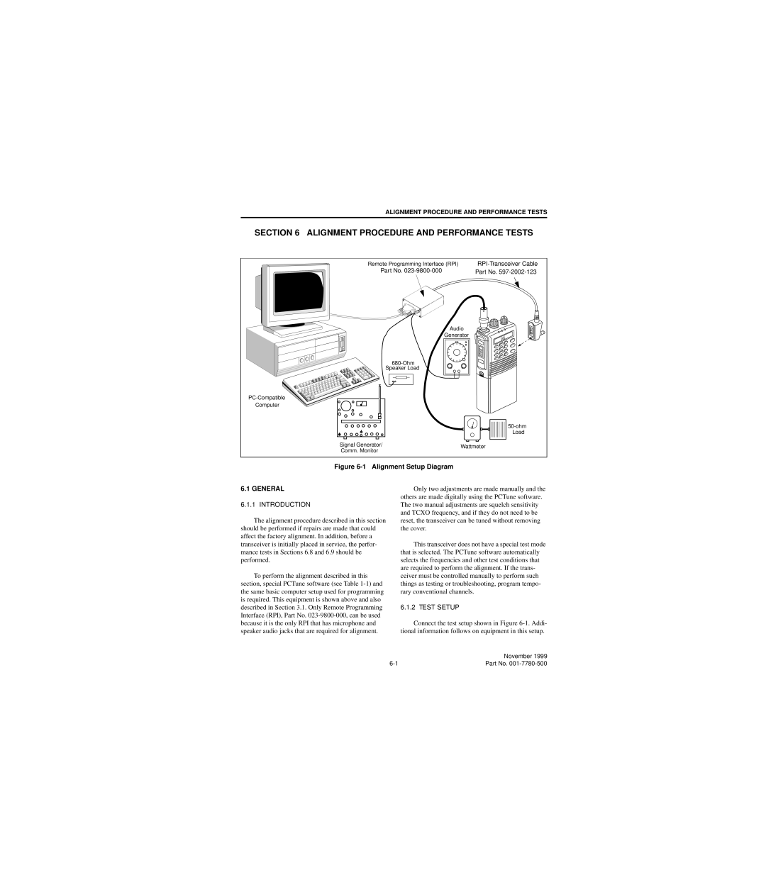
Figure 6-1 Alignment Setup Diagram
6.1 GENERAL
6.1.1 INTRODUCTION
The alignment procedure described in this section should be performed if repairs are made that could affect the factory alignment. In addition, before a transceiver is initially placed in service, the perfor- mance tests in Sections 6.8 and 6.9 should be performed.
To perform the alignment described in this section, special PCTune software (see Table
Only two adjustments are made manually and the others are made digitally using the PCTune software. The two manual adjustments are squelch sensitivity and TCXO frequency, and if they do not need to be reset, the transceiver can be tuned without removing the cover.
This transceiver does not have a special test mode that is selected. The PCTune software automatically selects the frequencies and other test conditions that are required to perform the alignment. If the trans- ceiver must be controlled manually to perform such things as testing or troubleshooting, program tempo- rary conventional channels.
6.1.2 TEST SETUP
Connect the test setup shown in Figure
| November 1999 |
Part No. |
