Service |
|
|
|
|
| ||
| 8 | 9110 | 1 | 23 | |||
Manual | 23. Timer | ||||||
Type | Edition | Page | |||||
|
|
|
|
|
|
| |
Description
Fig.
1
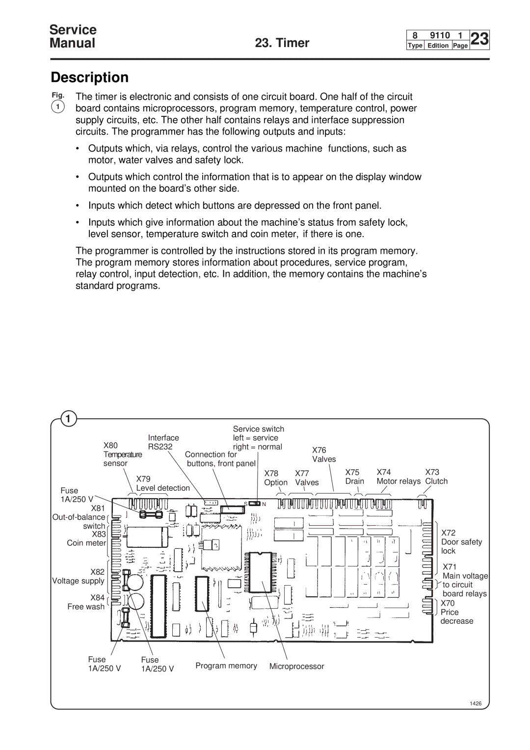
The timer is electronic and consists of one circuit board. One half of the circuit board contains microprocessors, program memory, temperature control, power supply circuits, etc. The other half contains relays and interface suppression circuits. The programmer has the following outputs and inputs:
•Outputs which, via relays, control the various machine functions, such as motor, water valves and safety lock.
•Outputs which control the information that is to appear on the display window mounted on the board’s other side.
•Inputs which detect which buttons are depressed on the front panel.
•Inputs which give information about the machine’s status from safety lock, level sensor, temperature switch and coin meter, if there is one.
The programmer is controlled by the instructions stored in its program memory. The program memory stores information about procedures, service program, relay control, input detection, etc. In addition, the memory contains the machine’s standard programs.
1
| Interface | Service switch |
|
|
|
| |
X80 | left = service |
|
|
|
| ||
RS232 | right = normal | X76 |
|
|
| ||
Temperature | Connection for |
|
|
|
| ||
| Valves |
|
|
| |||
sensor |
| buttons, front panel |
|
|
|
| |
|
|
| X75 | X74 | X73 | ||
| X79 |
| X78 | X77 | |||
|
| Option | Valves | Drain | Motor relays | Clutch | |
Fuse | Level detection |
|
|
|
|
| |
|
|
|
|
|
|
| |
1A/250 V |
| S | N |
|
|
|
|
X81 |
|
|
|
|
| ||
|
|
|
|
|
|
| |
|
|
|
|
|
|
| |
switch |
|
|
|
|
|
| X72 |
X83 |
|
|
|
|
|
| |
Coin meter |
|
|
|
|
|
| Door safety |
|
|
|
|
|
|
| lock |
X82 |
|
|
|
|
|
| X71 |
|
|
|
|
|
| Main voltage | |
Voltage supply |
|
|
|
|
|
| |
|
|
|
|
|
| to circuit | |
|
|
|
|
|
|
| |
X84 |
|
|
|
|
|
| board relays |
|
|
|
|
|
| X70 | |
Free wash |
|
|
|
|
|
| |
|
|
|
|
|
| Price | |
|
|
|
|
|
|
| |
|
|
|
|
|
|
| decrease |
Fuse | Fuse | Program memory | Microprocessor |
|
|
| |
1A/250 V | 1A/250 V |
|
|
| |||
|
|
|
|
|
| ||