Service
Manual | 12. Function Sequences |
10 | 9003 | 5 | 12 |
Type | Edition | Page |
Coin meter |
|
| COM |
B26 | NC |
| NO |
B25 | |
Parent card
B
X79:2 |
No coin meter
X79:1
X73
12 10
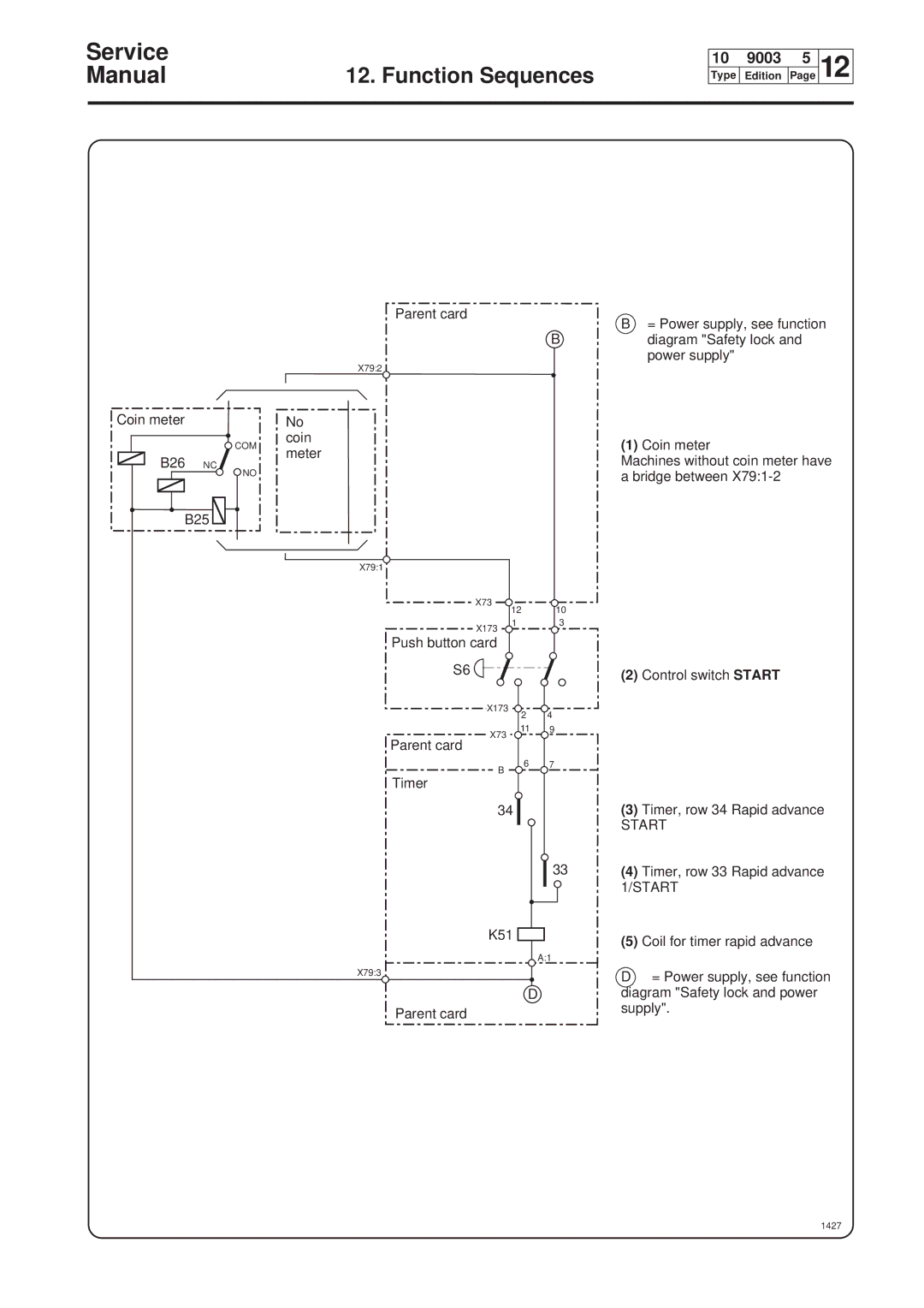
B= Power supply, see function diagram "Safety lock and power supply"
(1)Coin meter
Machines without coin meter have a bridge between
X173
Push button card
S6
1 3
(2)Control switch START
X173
2 4
X73
11 9
Parent card
B
Timer
6 7
34
33
K51
A:1
X79:3
D
Parent card
(3)Timer, row 34 Rapid advance
START
(4)Timer, row 33 Rapid advance 1/START
(5)Coil for timer rapid advance
D= Power supply, see function diagram "Safety lock and power supply".