Service |
|
|
|
|
| |
| 10 9003 11 | 12 | ||||
Manual | 12. Function Sequences |
|
|
| ||
Type | Edition | Page | ||||
|
|
|
|
|
|
|
Parent card |
| B |
|
|
|
| |
|
|
| A:17 |
Timer |
|
|
|
|
|
| 14 |
|
| a |
|
|
|
| a |
| X83 | 3 | 7 |
|
| ||
| X183 | 8 | 4 |
|
|
|
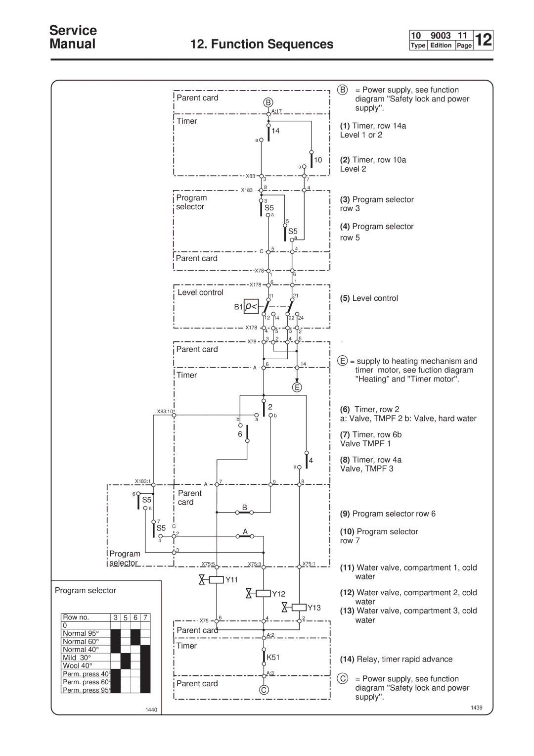
B= Power supply, see function diagram ''Safety lock and power supply''.
(1)Timer, row 14a Level 1 or 2
10(2) Timer, row 10a Level 2
Program |
| 3 |
| (3) Program selector |
selector |
| S5 |
| row 3 |
|
| a |
|
|
|
|
| 5 | (4) Program selector |
|
|
| S5 | |
|
|
| row 5 | |
|
|
| a | |
| C | 5 | 4 |
|
Parent card |
|
|
| |
|
|
|
| |
| X78 | 1 | 6 |
|
|
|
| ||
| X178 | 6 | 1 |
|
|
|
|
|
Level control
B1 p<
11 | 21 | (5) Level control |
|
|
|
|
|
|
| 12 | 14 | 22 | 24 |
|
|
|
| X178 | 4 | 5 | 3 | 2 |
|
|
|
|
| ||||
|
|
|
| X78 | 3 | 2 | 4 | 5 |
|
|
|
|
|
|
|
| |
|
| Parent card |
|
|
|
|
|
|
|
|
|
| A | 6 |
|
| 14 |
|
| Timer |
|
|
|
|
| |
|
|
|
|
|
|
|
| |
|
|
|
|
|
|
|
| E |
| X83:10 |
|
| 2 |
|
| ||
|
|
|
| b |
|
| ||
|
|
| b | a |
|
|
| |
|
|
|
|
|
|
| ||
|
|
| 6 |
|
|
|
|
|
|
|
|
|
|
|
|
| 4 |
|
|
|
|
|
|
| a | |
| X183:1 | A | 7 |
|
| 9 |
| 8 |
|
|
|
|
|
|
|
| |
| 6 | Parent |
|
|
|
|
|
|
| S5 | card |
| B |
|
|
|
|
| a |
|
|
|
|
|
| |
| 7 | C |
|
|
|
|
|
|
| S5 |
| A |
|
|
|
| |
|
| 2 |
|
|
|
|
| |
| a |
|
|
|
|
|
|
|
Program | 3 |
|
|
|
|
|
| |
|
|
|
|
|
|
| ||
selector | X75:5 |
| X75:3 |
|
|
| X75:1 | |
|
|
| Y11 |
|
|
|
|
|
Program selector |
|
|
|
| Y12 |
|
| |
|
|
|
|
|
|
|
| |
|
|
|
|
|
|
|
| Y13 |
Row no. | 3 5 6 7 | X75 | 6 |
| 4 |
|
| 2 |
0 |
|
|
|
|
|
|
| |
| Parent card |
|
|
|
|
|
| |
Normal 95° |
|
|
| A:2 |
|
| ||
|
|
|
|
|
| |||
Normal 60° |
| Timer |
|
|
|
|
|
|
Normal 40° |
|
|
|
|
|
|
| |
|
|
|
|
|
|
|
| |
Mild 30° |
|
|
|
| K51 |
|
| |
Wool 40° |
|
|
|
|
|
|
|
|
Perm. press 40° |
|
|
|
| A:3 |
|
| |
Perm. press 60° |
| Parent card |
|
| C |
|
|
|
Perm. press 95° |
|
|
|
|
|
|
| |
| 1440 |
|
|
|
|
|
|
|
E= supply to heating mechanism and timer motor, see fuction diagram ''Heating'' and ''Timer motor''.
(6)Timer, row 2
a: Valve, TMPF 2 b: Valve, hard water
(7)Timer, row 6b Valve TMPF 1
(8)Timer, row 4a Valve, TMPF 3
(9)Program selector row 6
(10)Program selector
row 7
(11)Water valve, compartment 1, cold water
(12)Water valve, compartment 2, cold water
(13)Water valve, compartment 3, cold water
(14)Relay, timer rapid advance
C= Power supply, see function diagram ''Safety lock and power supply''.