12![]()
![]() 11 9002 2
11 9002 2
Type Edition Page
| Service |
12. Operational sequences | Manual |
Service program setting
• Remove the top panel
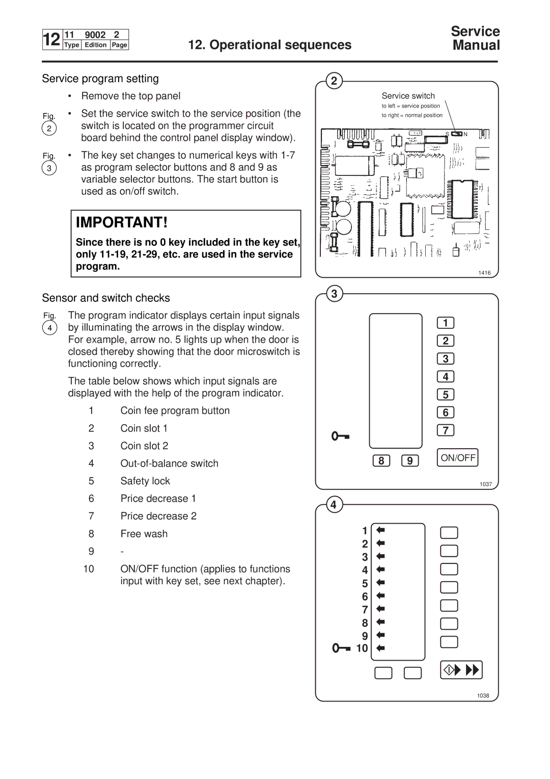
Fig. • Set the service switch to the service position (the
2switch is located on the programmer circuit board behind the control panel display window).
Fig. • The key set changes to numerical keys with 1-7
3as program selector buttons and 8 and 9 as variable selector buttons. The start button is used as on/off switch.
IMPORTANT!
Since there is no 0 key included in the key set, only
Sensor and switch checks
Fig. The program indicator displays certain input signals
4by illuminating the arrows in the display window. For example, arrow no. 5 lights up when the door is closed thereby showing that the door microswitch is functioning correctly.
The table below shows which input signals are displayed with the help of the program indicator.
1Coin fee program button
2Coin slot 1
3Coin slot 2
4Out-of-balance switch
5Safety lock
6Price decrease 1
7Price decrease 2
8Free wash
9-
10ON/OFF function (applies to functions input with key set, see next chapter).
2
Service switch
to left = service position
to right = normal position
S N
1416
3
1
2
3
4
5
6
7
8 9 ON/OFF
1037
4
1
2
3
4
5
6
7
8
9
![]() 10
10