12 | 12 | 9005 | 8 |
Type | Edition | Page |
| Service |
12. Function Sequence | Manual |
Safety Lock
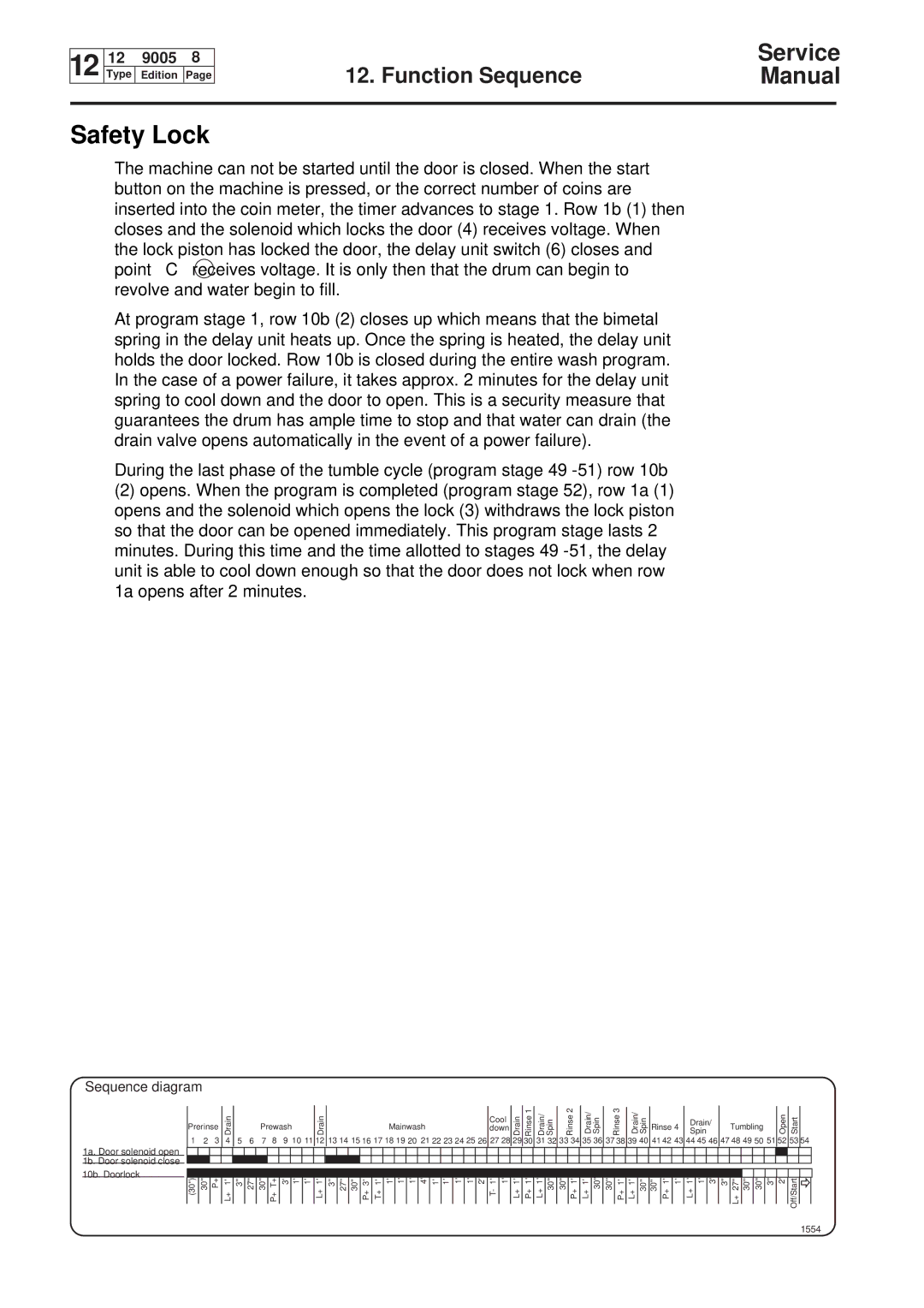
The machine can not be started until the door is closed. When the start button on the machine is pressed, or the correct number of coins are inserted into the coin meter, the timer advances to stage 1. Row 1b (1) then closes and the solenoid which locks the door (4) receives voltage. When the lock piston has locked the door, the delay unit switch (6) closes and point C receives voltage. It is only then that the drum can begin to revolve and water begin to fill.
At program stage 1, row 10b (2) closes up which means that the bimetal spring in the delay unit heats up. Once the spring is heated, the delay unit holds the door locked. Row 10b is closed during the entire wash program. In the case of a power failure, it takes approx. 2 minutes for the delay unit spring to cool down and the door to open. This is a security measure that guarantees the drum has ample time to stop and that water can drain (the drain valve opens automatically in the event of a power failure).
During the last phase of the tumble cycle (program stage 49
(2)opens. When the program is completed (program stage 52), row 1a (1) opens and the solenoid which opens the lock (3) withdraws the lock piston so that the door can be opened immediately. This program stage lasts 2 minutes. During this time and the time allotted to stages 49
Sequence diagram
1a. Door solenoid open
1b. Door solenoid close
10b. Doorlock
Prerinse | Drain |
|
| Prewash | Drain |
|
|
|
|
| Mainwash |
|
|
|
|
| down | Drain | Rinse1 | Drain/ Spin | Rinse2 | Drain/ Spin |
| Rinse3 | Drain/ Spin | Rinse 4 | Spin |
|
| Tumbling |
| Open | Start |
| |||||||||||||||||||
|
|
|
|
|
|
|
|
|
|
|
|
|
|
|
|
|
|
|
|
|
|
|
|
|
| Cool |
|
|
|
|
|
|
|
|
|
|
|
|
|
|
| Drain/ |
|
|
|
|
|
|
|
| |||
|
|
|
|
|
|
|
|
|
|
|
|
|
|
|
|
|
|
|
|
|
|
|
|
|
|
|
|
|
|
|
|
|
|
|
|
|
|
|
|
|
|
|
|
|
|
|
|
|
|
| |||
1 | 2 | 3 | 4 | 5 | 6 | 7 | 8 | 9 10 11 | 12 | 13 14 15 16 17 18 19 20 21 22 23 24 25 26 | 27 28 | 29 | 30 | 31 32 | 33 | 34 | 35 36 | 37 38 | 39 40 | 41 42 43 | 44 45 | 46 | 47 48 49 50 |
|
| 53 | 54 | ||||||||||||||||||||||||||
|
|
|
|
|
|
|
|
|
|
|
|
|
|
|
|
|
|
|
|
|
|
|
|
|
|
|
|
|
|
|
|
|
|
|
|
|
|
|
|
|
|
|
|
|
|
|
|
|
|
|
|
|
|
|
|
|
|
|
|
|
|
|
|
|
|
|
|
|
|
|
|
|
|
|
|
|
|
|
|
|
|
|
|
|
|
|
|
|
|
|
|
|
|
|
|
|
|
|
|
|
|
|
|
|
|
|
|
|
|
|
|
|
|
|
|
|
|
|
|
|
|
|
|
|
|
|
|
|
|
|
|
|
|
|
|
|
|
|
|
|
|
| |||||||||||||||||||
|
|
|
|
|
|
|
|
|
|
|
|
|
|
|
|
|
|
|
|
|
|
|
|
|
|
|
|
|
|
|
|
|
|
|
|
|
|
|
|
|
|
|
|
|
|
|
|
|
|
|
|
| |
(30'') | 30'' | P+ | L+ 1' | 3'' | 27'' | 30'' | P+ T+ | 3' 1' 1' | L+ 1' | 3'' 27'' 30'' P+ 3' | T+ 1' 1' 1' 1' 4' | 1' 1' | 1' | 1' 2' T- 1' 1' | L+ 1' | P+ 1' | L+ 1' 30'' | 30'' | P+ 1' | L+ 1' 30'' | 30'' | P+ 1' | L+ 1' 30'' | 30'' P+ 1' 1' | L+ 1' 1' | 3' | 3'' L+ 27'' 30'' 30'' | 3'' 2' | Off/Start | ||||||||||||||||||||||||