Service |
|
|
|
|
| |
| 10 9003 13 | 12 | ||||
Manual | 12. Function Sequences |
|
|
| ||
Type | Edition | Page | ||||
|
|
|
|
|
|
|
Timer
E
5
![]() b
b
X83:6
X183:5
Programselector
9
S5
![]() a
a
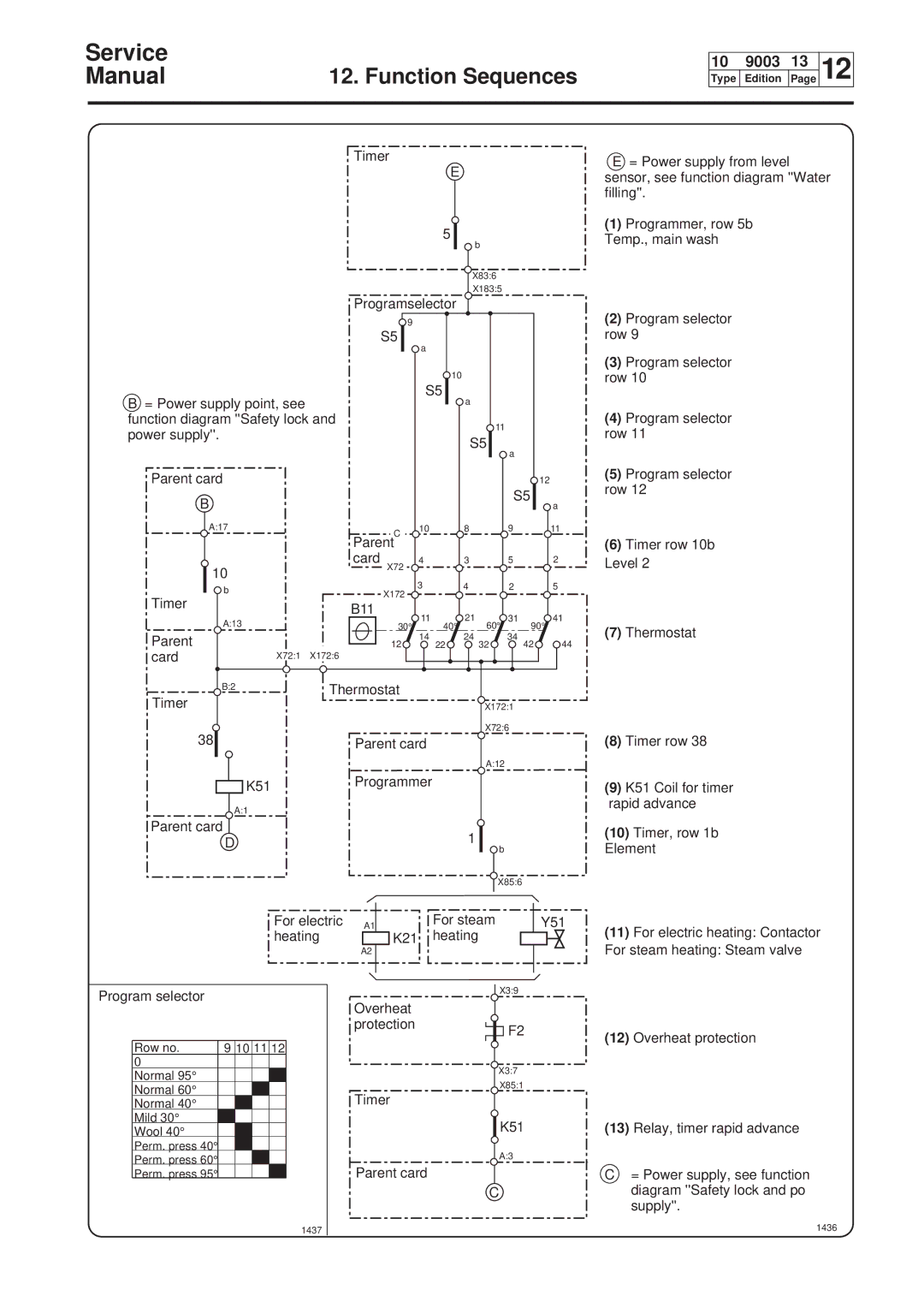
E= Power supply from level sensor, see function diagram ''Water filling''.
(1)Programmer, row 5b Temp., main wash
(2)Program selector row 9
B= Power supply point, see function diagram ''Safety lock and power supply''.
Parent card
B
A:17
10
S5
C 10
Parent
card 4
X72
10
a
S5
8
3
11
a
S5
9
5
(3)Program selector row 10
(4)Program selector row 11
12(5) Program selector
row 12
a
11
(6)Timer row 10b
2Level 2
b | 3 | 4 | 2 | 5 |
X172 |
|
|
| |
|
|
|
|
Timer | B11 |
|
|
|
|
|
| 21 60° |
|
| |
A:13 | 30° 11 | 40° | 31 90° | 41 | |
Parent | 14 |
| 24 | 34 | (7) Thermostat |
12 | 22 | 32 | 42 | 44 | |
card | X72:1 X172:6 |
|
|
|
|
B:2 | Thermostat |
|
|
|
|
Timer |
|
|
|
| |
|
| X172:1 |
| ||
38 |
|
| X72:6 | (8) Timer row 38 | |
Parent card |
|
|
| ||
|
|
| A:12 |
|
|
K51Programmer
(9) K51 Coil for timer |
rapid advance |
A:1
Parent card
D
For electric | A1 |
heating | K21 |
| A2 |
1
![]() b
b
X85:6
For steam | Y51 |
heating |
|
(10) | Timer, row 1b |
Element | |
(11) | For electric heating: Contactor |
For steam heating: Steam valve | |
Program selector
Row no. | 9 | 10 | 11 | 12 |
0 |
|
|
|
|
Normal 95° |
|
|
|
|
Normal 60° |
|
|
|
|
Normal 40° |
|
|
|
|
Mild 30° |
|
|
|
|
Wool 40° |
|
|
|
|
Perm. press 40°
Perm. press 60°
Perm. press 95°
X3:9
Overheat
protectionF2
X3:7
X85:1
Timer
K51
A:3
Parent card
C
(12) | Overheat protection |
(13) | Relay, timer rapid advance |
C= Power supply, see function diagram ''Safety lock and po supply''.