Service
Manual | 12. Function Sequences |
12 9005 15 12
Type Edition Page
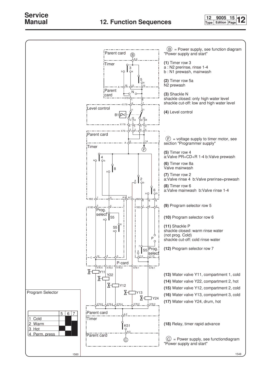
Program Selector
5 | 6 | 7 |
1Cold
2Warm
3 Hot
4 Perm. press
1560
|
| Parent card |
|
| B |
|
|
| |
|
|
|
|
|
|
|
|
| |
|
|
|
|
|
| A:4 |
|
|
|
|
| Timer |
| 3 |
|
|
|
| |
|
|
|
|
|
|
|
| ||
|
|
| b |
|
| a |
|
|
|
|
|
|
|
|
|
| 5 |
|
|
|
|
|
|
|
|
| a |
|
|
|
|
| 16 |
|
| 12 | 15 |
| |
|
| Parent | A |
|
|
|
|
|
|
|
|
|
|
| N |
|
|
| |
|
| card |
|
|
|
|
|
| |
|
| X79 |
|
|
|
|
|
| |
|
|
|
| 1 | 6 |
|
| ||
|
|
|
|
|
|
| |||
|
|
| X179 |
|
| 6 | 1 |
|
|
Level control |
|
|
|
|
|
| |||
|
| 11 | 21 |
| |||||
|
| B1 p< |
|
|
|
|
|
| |
|
|
|
| 12 | 14 | 22 | 24 |
| |
|
|
| X179 | 4 |
| 5 | 3 | 2 |
|
|
|
|
|
|
| ||||
|
|
| X79 | 3 |
| 2 | 4 | 5 |
|
Parent card |
|
|
|
|
|
| |||
|
|
|
|
|
|
| |||
|
|
| A | 6 |
|
|
| 14 |
|
|
|
|
|
|
|
|
|
| |
Timer |
|
|
|
|
| F |
| ||
|
|
|
|
|
|
|
| ||
| a | 4 |
|
|
|
|
|
|
|
| b |
|
|
|
|
|
|
| |
|
| 8 |
|
|
|
|
|
|
|
|
| a |
|
|
|
|
|
|
|
|
|
|
|
|
| a | 2 |
|
|
|
|
|
|
|
|
| b |
|
|
|
|
|
|
|
|
|
|
| 6 |
|
|
|
|
|
|
|
| a | b |
X82 | 7 | 5 | A:9 A:7 |
|
|
| |||
|
|
|
|
| X82 | 9 | 6 | 8 | |
|
|
|
|
|
|
| |||
X182 | 3 | 5 |
|
|
| X182 | 1 | 4 | 2 |
Prog. |
|
|
|
|
|
| |||
|
|
|
|
|
|
|
| ||
select5
| a | S5 |
|
|
|
|
|
|
|
| |
|
|
| 6 |
|
|
|
| S5 |
|
| |
|
| a |
|
|
|
|
|
|
|
| P |
|
|
|
| 7 | S5 Prog. |
|
|
|
| a | |
| 14 | 4 |
|
| select |
C | 3 | C:2 | C:13 | ||
|
|
|
|
| |
|
|
|
|
| |
| X76:5 | X78:3 | X76:3 | X76:1 | X78:1 |
| Y11 | Y22 |
|
|
|
|
|
|
|
| |
|
|
| Y12 |
|
|
|
|
|
| Y13 |
|
|
|
|
|
| Y24 |
| X76:6 | X78:4 | X76:4 | X76:2 | X78:2 |
Parent card | A:2 |
|
| ||
|
|
|
|
| |
Timer |
|
|
|
| |
|
|
| K51 |
|
|
|
|
| A:3 |
|
|
Parent card
C
B= Power supply, see function diagram "Power supply and start"
(1)Timer row 3
a : N2 prerinse, rinse
b : N1 prewash, mainwash
(2)Timer row 5a
N2 prewash
(3)Shackle N
shackle closed: only high water level
shackle
(4)Level control
F= voltage supply to timer motor, see section "Programmer supply"
(5)Timer row 4
a:Valve PR+CD+R
(6)Timer row 8a Valve mainwash
(7)Timer row 2
a:Valve rinse 4 b:Valve prerinse+prewash
(8)Timer row 6
a:Valve mainwash b:Valve rinse
(9)Program selector row 5
(10)Program selector row 6
(11)Shackle P
shackle closed: warm rinse water (not prog. Cold)
shackle
(12)Program selector row 7
(13)Water valve Y11, compartment 1, cold
(14)Water valve Y22, compartment 2, hot
(15)Water valve Y12, compartment 2, cold
(16)Water valve Y13, compartment 3, cold
(17)Water valve Y24, drum, hot
(18)Relay, timer rapid advance
C= Power supply, see functiondiagram "Power supply and start"