Service |
|
|
|
|
|
|
| |
3. Description of principle components | 11 |
| 9020 |
| 1 | 3 | ||
Manual |
|
| ||||||
|
|
|
|
| ||||
Type | Edition | Page | ||||||
|
|
|
|
|
|
|
|
|
Fig.
1
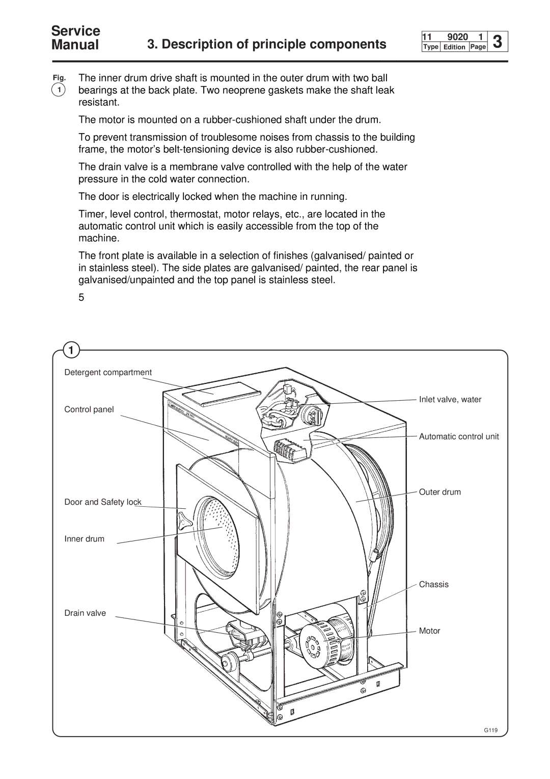
The inner drum drive shaft is mounted in the outer drum with two ball bearings at the back plate. Two neoprene gaskets make the shaft leak resistant.
The motor is mounted on a
To prevent transmission of troublesome noises from chassis to the building frame, the motor’s
The drain valve is a membrane valve controlled with the help of the water pressure in the cold water connection.
The door is electrically locked when the machine in running.
Timer, level control, thermostat, motor relays, etc., are located in the automatic control unit which is easily accessible from the top of the machine.
The front plate is available in a selection of finishes (galvanised/ painted or in stainless steel). The side plates are galvanised/ painted, the rear panel is galvanised/unpainted and the top panel is stainless steel.
5
1
Detergent compartment
Inlet valve, water
Control panel
Automatic control unit
Outer drum
Door and Safety lock
Inner drum
Chassis
Drain valve
Motor