Service |
|
|
|
|
| |
| 12 9005 13 | 12 | ||||
Manual | 12. Function Sequences |
|
|
| ||
Type | Edition | Page | ||||
|
|
|
|
|
|
|
Program Selector
8 10
1 Cold
2Warm
3Hot
4Perm. press
Parent Card
|
|
|
|
|
|
| B |
|
|
|
|
|
|
| A:4 | C:12 |
| C:10 |
| ||
|
|
|
|
| Prog. |
|
| 8 |
| |
|
|
|
|
| selector |
|
| |||
|
|
|
|
| S5 |
| ||||
|
|
|
|
|
|
|
| a |
|
|
|
|
|
|
|
| 10 |
|
|
|
|
|
|
|
|
|
| S5 |
|
|
|
|
|
|
|
|
|
| a |
|
|
|
|
|
|
|
| X83:5 | X182:8 | X182:9 | ||||
|
|
|
| X83:6 | X82:2 | X82:1 | ||||
|
|
|
|
| b | 22 |
|
|
| |
|
|
|
|
|
|
|
|
|
| |
|
|
|
| a |
|
|
|
|
|
|
|
|
|
|
| 11 |
|
|
|
|
|
|
|
|
| a |
| b |
|
|
|
|
|
|
|
| 14 |
|
|
|
|
| |
|
| 13 |
|
|
|
|
|
|
|
|
b |
|
|
| b |
|
|
|
|
|
|
|
|
|
|
|
|
|
|
|
| |
|
|
|
| 24 |
|
|
|
|
|
|
X85 | 3 |
|
| 4 | Timer |
|
|
| ||
|
|
|
|
|
|
|
|
|
| |
|
|
|
| A1 |
|
|
|
|
|
|
|
|
|
| K1 |
|
|
|
|
| |
|
|
|
| A2 |
|
|
|
|
|
|
K4 | A1 |
|
|
|
|
|
|
|
|
|
A2 |
|
|
|
|
|
|
|
|
| |
|
|
|
|
|
|
|
|
|
| |
|
|
|
| 22 |
|
|
|
|
|
|
|
|
|
| K4 |
|
|
|
|
| |
|
|
|
| 21 |
|
|
|
|
|
|
|
|
|
| X3:9 |
|
|
|
|
| |
Overheat |
|
|
|
|
|
|
| |||
protection | F2 |
|
|
|
|
| ||||
|
|
|
|
|
|
|
|
| ||
|
|
|
| X3:7 |
|
|
|
|
|
|
|
|
|
| X85:1 |
|
|
|
|
| |
Timer |
|
|
|
|
|
|
|
| ||
|
|
|
| K51 |
|
|
|
|
| |
|
|
|
| A:3 |
|
|
|
|
|
|
Parent |
|
|
|
|
|
|
|
| ||
Card |
|
| C |
|
|
|
|
|
| |
L1 |
|
|
|
|
| 311 |
|
|
|
|
|
|
|
|
| 312 |
|
|
|
| |
L2 |
|
|
|
|
|
|
|
|
| |
|
|
|
|
| 313 |
|
|
|
| |
L3 |
|
|
|
|
|
|
|
|
| |
|
|
|
| 2 |
|
|
|
|
| |
|
| 6 |
| 4 |
|
|
|
|
| |
|
|
|
|
| K1 |
|
|
|
|
|
|
| 5 |
| 3 | 1 |
|
|
|
|
|
| 323 |
| 324 | 303 |
|
| 6 |
| 4 | 2 |
|
|
|
|
|
|
|
| |||
X25 | 3 |
| 4 |
|
|
|
|
|
| |
|
|
|
|
| 5 |
| 3 | 1 | ||
Timer |
|
|
|
|
| 306 |
| |||
|
|
|
|
|
| 305 |
| 304 | ||
|
| 21 |
| 23 |
|
|
| |||
|
|
|
| X3 | 6 |
| 5 | 4 | ||
|
|
|
|
|
|
|
|
|
| |
| a | b | a | b | Motor |
|
|
|
| |
|
|
|
|
|
| |||||
X25 | 1 |
| 2 |
|
|
|
| M M1 | ||
|
|
|
|
|
|
|
| |||
|
|
|
|
|
|
|
|
| ||
| 301 |
| 302 |
|
| X3 | 3 |
| 2 | 1 |
|
|
|
|
|
|
|
| |||
|
|
|
|
|
|
|
|
| ||
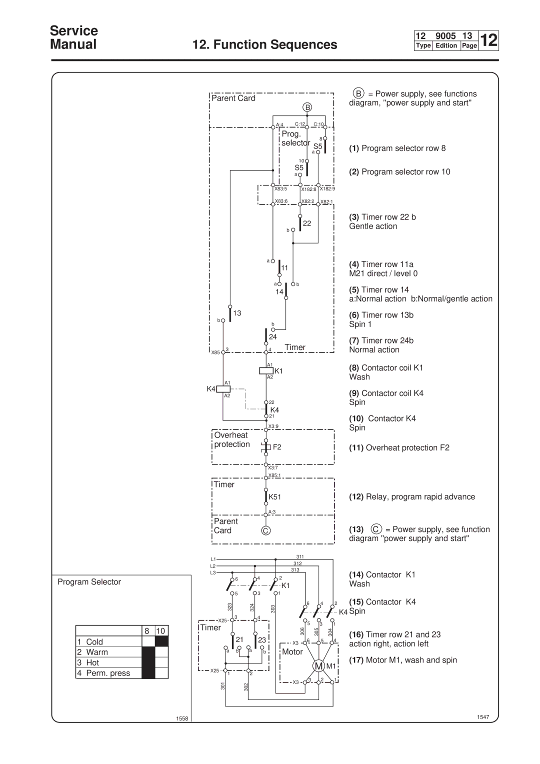
B= Power supply, see functions diagram, ''power supply and start''
(1)Program selector row 8
(2)Program selector row 10
(3)Timer row 22 b
Gentle action
(4)Timer row 11a M21 direct / level 0
(5)Timer row 14
a:Normal action b:Normal/gentle action
(6)Timer row 13b Spin 1
(7)Timer row 24b Normal action
(8)Contactor coil K1 Wash
(9)Contactor coil K4 Spin
(10)Contactor K4
Spin
(11)Overheat protection F2
(12)Relay, program rapid advance
(13)C = Power supply, see function diagram ''power supply and start''
(14)Contactor K1
Wash
(15)Contactor K4
K4 Spin
(16)Timer row 21 and 23 action right, action left
(17)Motor M1, wash and spin