12 | 12 | 9005 | 12 |
Type | Edition | Page |
| Service |
12. Function Sequences | Manual |
Motor control
Normal Action (12 second rotation - 3 second pause)
Row 8 (1) in the program selector is closed during programs ”Warm”, ”Hot” and ”Permanent Press” when the motor is running at normal action. From row 8 the voltage is supplied via row 14b (5) to row 24b (7). This row is located in the timer's
Gentle Action (3 second rotation - 12 second pause)
Row 10 (2) in the program selector is closed and row 8 (1) is
Spin
During the spin cycle, row 13b (6) activates spin contactor K4 (9). At the same time K4:21
Normal action during tumbling
At stage 48, contactor K1 is supplied via row 14a (5) instead of 14b. The motor runs at normal speed at this stage regardless of which program has been chosen.
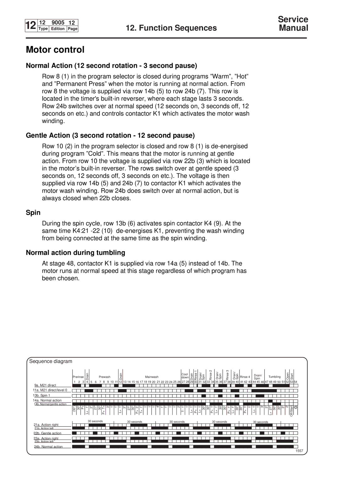
Sequence diagram
9a. M21 direct
11a. M21 direct/level 0
13b. Spin 1
14a. Normal action
14b. Normal/gentle action
21a. Action right
21b. Action left
22b. Gentle action
23a. Action right
23b. Action left
24b. Normal action
Prerinse | Drain |
|
| Prewash |
|
| Drain |
|
|
|
|
|
| Mainwash |
|
|
|
|
| down | Drain | Rinse1 | Drain/ Spin | Rinse2 | Drain/ Spin |
| Rinse3 | Drain/ Spin | Rinse 4 | Spin |
|
| Tumbling |
| Open | Start |
| ||||||||||||||||||||
|
|
|
|
|
|
|
|
|
|
|
|
|
|
|
|
|
|
|
|
|
|
|
|
|
|
|
| Cool |
|
|
|
|
|
|
|
|
|
|
|
|
|
|
|
| Drain/ |
|
|
|
|
|
|
|
|
| |||
1 | 2 | 3 | 4 | 5 | 6 | 7 | 8 | 9 | 10 11 |
| 12 | 13 14 15 16 17 18 19 20 21 22 23 24 25 26 | 27 28 |
|
| 31 32 | 33 34 |
|
| 35 36 |
|
| 39 40 | 41 42 43 | 44 45 |
| 47 48 |
|
|
|
|
| 53 | 54 | |||||||||||||||||||||||
|
|
|
|
|
|
|
|
|
|
|
|
|
|
|
|
|
|
|
|
|
|
|
|
|
|
|
|
|
|
|
|
|
|
|
|
|
|
|
|
|
|
|
|
|
|
|
|
|
|
|
|
|
|
|
|
|
|
|
|
|
|
|
|
|
|
|
|
|
|
|
|
|
|
|
|
|
|
|
|
|
|
|
|
|
|
|
|
|
|
|
|
|
|
|
|
|
|
|
|
|
|
|
|
|
|
|
|
|
|
|
|
|
|
|
|
|
|
|
|
|
|
|
|
|
|
|
|
|
|
|
|
|
|
|
|
|
|
|
|
|
|
|
|
|
|
|
|
|
|
|
|
|
|
|
|
|
|
|
|
|
|
|
|
|
|
|
|
|
|
|
|
|
|
|
|
|
|
|
|
|
|
|
|
|
|
|
|
|
|
|
|
|
|
|
|
|
|
|
|
|
|
|
|
|
|
|
|
|
|
|
|
|
|
|
|
|
|
|
|
|
|
|
|
|
|
|
|
|
|
|
|
|
|
|
|
|
|
|
|
|
|
|
|
|
|
|
|
|
|
|
|
|
|
|
|
|
|
|
|
|
|
|
|
|
|
|
|
|
|
|
|
|
|
|
|
|
|
|
|
|
|
|
|
|
|
|
|
|
|
|
|
|
|
|
|
|
|
|
|
|
|
|
|
|
|
|
|
|
|
|
|
|
|
|
|
|
|
|
|
|
|
|
|
|
|
|
|
|
|
|
|
|
|
|
|
|
|
|
|
|
|
|
|
|
|
|
|
|
|
|
|
|
|
|
|
|
|
|
|
|
|
|
|
|
|
|
|
|
|
|
|
|
|
|
|
|
|
|
|
|
|
|
|
|
|
|
|
|
|
|
|
|
|
|
|
|
|
|
|
|
|
|
|
|
|
|
|
|
|
|
|
|
|
|
|
|
|
|
|
|
|
|
|
|
|
|
|
|
|
|
|
|
|
|
|
|
|
|
|
|
|
|
|
|
|
|
|
|
|
|
|
|
|
|
|
|
|
|
|
|
|
|
|
(30'') | 30'' | P+ | L+ 1' | 3'' | 27'' | 30'' | P+ T+ | 3' | 1' 1' | L+ 1' | 3'' | 27'' | 30'' | P+ 3' | T+ 1' | 1' | 1' | 1' |
| 4' | 1' 1' | 1' 1' 2' T- 1' 1' | L+ 1' | P+ 1' | L+ 1' 30'' | 30'' | P+ 1' | L+ 1' 30'' 30'' | P+ 1' | L+ 1' 30'' | 30'' P+ 1' 1' | L+ 1' 1' | 3' | 3'' L+ 27'' | 30'' 30'' | 3'' | 2' | Off/Start | |||||||||||||||||||
|
|
| 30 seconds |
|
|
|
|
|
| 30 seconds |
|
|
|
| 30 seconds |
|
|
|
|
| 30 seconds |
|
|
|
|
| 30 seconds |
|
|
|
|
|
|
| |||||||||||||||||||||||
|
|
|
|
|
|
|
|
|
|
|
|
|
|
|
|
|
|
|
|
|
|
|
|
|
|
|
|
| |||||||||||||||||||||||||||||
|
|
|
|
|
|
|
|
|
|
|
|
|
|
|
|
|
|
|
|
|
|
|
|
|
|
|
|
|
|
|
|
|
|
|
|
|
|
|
|
|
|
|
|
|
|
|
|
|
|
|
|
|
|
|
|
|
|
|
|
|
|
|
|
|
|
|
|
|
|
|
|
|
|
|
|
|
|
|
|
|
|
|
|
|
|
|
|
|
|
|
|
|
|
|
|
|
|
|
|
|
|
|
|
|
|
|
|
|
|
|
|
|
|
|
|
|
|
|
|
|
|
|
|
|
|
|
|
|
|
|
|
|
|
|
|
|
|
|
|
|
|
|
|
|
|
|
|
|
|
|
|
|
|
|
|
|
|
|
|
|
|
|
|
|
|
|
|
|
|
|
|
|
|
|
|
|
|
|
|
|
|
|
|
|
|
|
|
|
|
|
|
|
|
|
|
|
|
|
|
|
|
|
|
|
|
|
|
|
|
|
|
|
|
|
|
|
|
|
|
|
|
|
|
|
|
|
|
|
|
|
|
|
|
|
|
|
|
|
|
|
|
|
|
|
|
|
|
|
|
|
|
|
|
|
|
|
|
|
|
|
|
|
|
|
|
|
|
|
|
|
|
|
|
|
|
|
|
|
|
|
|
|
|
|
|
|
|
|
|
|
|
|
|
|
|
|
|
|
|
|
|
|
|
|
|
|
|
|
|
|
|
|
|
|
|
|
|
|
|
|
|
|
|
|
|
|
|
|
|
|
|
|
|
|
|
|
|
|
|
|
|
|
|
|
|
|
|
|
|
|
|
|
|
|
|
|
|
|
|
|
|
|
|
|
|
|
|
|
|
|
|
|
|
|
|
|
|
|
|
|
|
|
|
|
|
|
|
|
|
|
|
|
|
|
|
|
|
|
|
|
|
|
|
|
|
|
|
|
|
|
|
|
|
|
|
|
|
|
|
|
|
|
|
|
|
|
|
|
|
|
|
|
|
|
|
|
|
|
|
|
|
|
|
|
|
|
|
|
|
|
|
|
|
|
|
|
|
|
|
|
|
|
|
|
|
|
|
|
|
|
|
|
|
|
|
|
|
|
|
|
|
|
|
|
|
|
|
|
|
|
|
|
|
|
|
|
|
|
|
|
|
|
|
|
|
|
|
|
|
|
|
|
|
|
|
|
|
|
|
|
|