Service
Manual | 12. Function Sequences |
10 | 9003 | 9 | 12 |
Type | Edition | Page |
Parent card
A B E
A | 16 | 15 | 14 |
|
|
|
Timer
a
7
![]() a
a
5
11
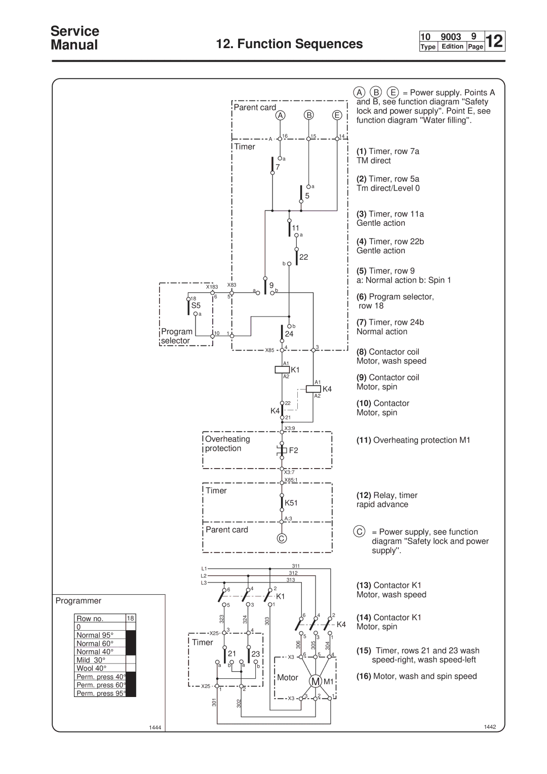
AB E = Power supply. Points A and B, see function diagram ''Safety lock and power supply''. Point E, see function diagram ''Water filling''.
(1) | Timer, row 7a |
TM direct | |
(2) | Timer, row 5a |
Tm direct/Level 0 | |
(3) | Timer, row 11a |
Gentle action | |
| X183 | X83 |
|
| |
18 | 6 | 5 |
|
| |
S5 |
|
|
a |
|
|
Program | 10 | 1 |
selector |
|
|
a
|
| 22 |
|
|
| b |
|
a | 9 | b |
|
|
| ||
|
| b |
|
|
| 24 |
|
| X85 | 4 | 3 |
|
|
| |
|
| A1 |
|
|
| K1 |
|
|
| A2 |
|
|
|
| A1 |
(4) | Timer, row 22b |
Gentle action | |
(5) | Timer, row 9 |
a: Normal action b: Spin 1
(6) | Program selector, |
row 18 | |
(7) | Timer, row 24b |
Normal action | |
(8) | Contactor coil |
Motor, wash speed | |
(9) | Contactor coil |
K4
A2
22
K4
![]() 21
21
X3:9
Overheating
protectionF2
Motor, spin | |
(10) | Contactor |
Motor, spin | |
(11) | Overheating protection M1 |
Programmer
Row no. | 18 |
0 |
|
Normal 95° |
|
Normal 60° |
|
Normal 40° |
|
Mild 30° |
|
Wool 40° |
|
Perm. press 40°
Perm. press 60°
Perm. press 95°
1444
X3:7
X85:1
Timer
K51
A:3
Parent card
|
|
|
|
| C |
|
|
|
L1 |
|
|
|
| 311 |
|
|
|
|
|
|
| 312 |
|
|
| |
L2 |
|
|
|
|
|
|
| |
|
|
|
| 313 |
|
|
| |
L3 |
|
|
|
|
|
|
| |
|
|
|
| 2 |
|
|
| |
|
| 6 |
| 4 |
|
|
| |
|
|
|
|
| K1 |
|
|
|
|
| 5 |
| 3 | 1 |
|
|
|
| 323 |
| 324 |
| 303 | 6 | 4 | 2 |
|
|
|
|
| K4 | |||
|
| 3 |
| 4 |
|
|
| |
X25 |
|
|
|
|
| |||
|
|
|
| 5 | 3 | 1 | ||
Timer |
|
|
|
| 306 | |||
|
|
|
|
| 305 | 304 | ||
|
| 21 |
| 23 |
| |||
|
|
| X3 | 6 | 5 | 4 | ||
|
|
|
|
|
|
|
| |
| a | b | a | b |
|
|
|
|
|
|
|
|
| Motor |
| M M1 | |
X25 | 1 |
| 2 |
|
|
| ||
|
|
|
|
|
| |||
|
|
|
|
|
|
| ||
301 |
|
| 302 |
| X3 | 3 | 2 | 1 |
|
|
|
|
|
| |||
|
|
|
|
|
|
| ||
(12)Relay, timer rapid advance
C= Power supply, see function diagram ''Safety lock and power supply''.
(13)Contactor K1 Motor, wash speed
(14)Contactor K1 Motor, spin
(15)Timer, rows 21 and 23 wash
(16)Motor, wash and spin speed