IB-106-340 Rev December
Oxymitter
Essential Instructions
Summary
Highlights of Changes
Effective December, 2003 Rev
Highlights of Changes
Oxymitter
Table of Contents
Startup and Operation of Oxymitter 4000 with LOI
Oxymitter 4000 Gas Connections Calibration Gas Connections
List of Illustrations
11-1
List of Tables
11-3
11-5
Definitions
Preface
Oxymitter
Belangrijk
Vigtigt
Oxymitter
Tärkeää
Oxymitter
Wichtig
Importante
Viktig
Oxymitter
Oxymitter
Viktigt
Oxymitter
July 1
Ceramic Fiber Products Material Safety Data Sheet
Section II. Physical Data
Section V. Health Hazard Data
Section VI. Reactivity Data
Section VII. Spill or Leak Procedures
Section IX. Special Precautions
Oxymitter
Oxymitter 4000 with Remote Imps 4000 Option
What YOU Need to Know
Oxymitter Remote Electronics with Integral SPS Option
Use this Quick Start Guide if
Can YOU USE the Following Quick Start GUIDE?
Quick Start Guide For Oxymitter 4000 Systems
Oxymitter 4000 with SPS 4000 Wiring Diagram
Performing a Manual Calibration with a Membrane Keypad
Quick Reference Guide Manual Calibration Instructions
Technical Support Hotline
Hart Communicator Fast KEY Sequences
System Overview
Section Description and Specifications
Component Checklist of Typical System Package Contents
Typical System Package
Remote Mounted
Oxymitter Integrally Mounted
Membrane Keypad
Model 751 LCD Display Panel
Control Room Asset Management Solutions Line Voltage
SPS 4000 Single Probe Autocalibration Option
Standard
Imps 4000 Multiprobe
Autocalibration Option
Calibra
Components Figure
Imps 4000 Optional
SPS 4000 Optional
Mounting
Rear View of Manifold only
Front View
Diffusion Elements
Model 751 Remote Powered Loop LCD Display
Probe Options
Abrasive Shield Assembly
13. Hastelloy Cup-Type Diffusion Assembly
View a
Specifications Oxymitter
90 to 250 VAC, 50/60 Hz
100% relative humidity
Nema 4X IP56
In. NPT
Code Sensing Probe Type
Product Matrix
Part Number Description
Calibration Components
3D39695G04
3D39695G01
3D39695G02
3D39695G03
Selecting Location
Section Installation
Mechanical Installation
Oxymitter 4000 Probe Installation
Oxymitter 4000 Remote Electronics Installation
Vertical Mounted SPS 4000 a
Horizontal Mounted SPS 4000 a
Oxymitter 4000 with Abrasive Shield
Oxymitter 4000 Adapter Plate Dimensions
Oxymitter 4000 Adapter Plate Installation
Oxymitter 4000 Abrasive Shield Bracing Installation
Installation with Drip Loop and Insulation Removal
Remote Electronics Installation
Connect Line Voltage
All wiring must conform to local and national codes
Integral Electronics
Install Interconnecting Cable
Probe
WALL-MOUNTED
Electrical Installation for Oxymitter 4000 with SPS
Not Used Line
Reference Air Package
Connect Relay Output Wiring
Connect 4-20 mA Signal Wiring
Pneumatic Installation for Oxymitter 4000 Without SPS
13. Air Set, Plant Air Connection
Imps 4000 Connections
Pneumatic Installation for
Oxymitter 4000 with SPS
Oxymitter
General
Section Configuration of Oxymitter With Membrane Keypad
Verify Mechanical Installation
Verify Terminal Block Wiring
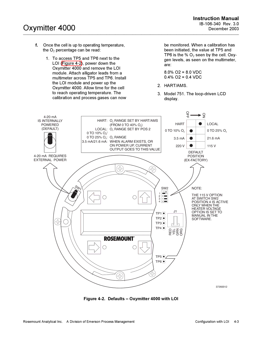
Model 751. The loop-driven LCD display
Verify Oxymitter 4000 Configuration
SW2
Heater T/C Diagnostic
Logic I/O
Alarm
Calibration Handshake Signal
Logic I/O Configuration as set at HART/AMS or LOI Mode
Calibration
Recommended Configuration
MA Signal Upon Critical Alarm
Oxymitter
Electronics Housing Terminals and LOI
Section Configuration of Oxymitter 4000 with LOI
Verify Oxymitter 4000 Configuration
Defaults Oxymitter 4000 with LOI
Logic I/O
Recommended Configuration
Oxymitter
General Operation
Power UP
Case of multiple errors, only one
Diagnostic Alarm LEDS. If there
Is an error in the system, one of these
TROUBLESHOOTING.
Start UP Oxymitter 4000 Calibration
Section Startup and Operation Oxymitter 4000 with LOI
O2 0.00% LK warm up 367dgC
O2 2.59% LK normal
Lockout
LOI Features
Data
LOI Menu Tree
SYSTEM/Calibration Setup
Oxymitter 4000 Setup AT the LOI
SYSTEM/Parameters
SYSTEM/Input/Output
Sensor Data
LOI Installation
SYSTEM/Status
SYSTEM/Software
TP1 and TP2 monitor the oxygen cell
Model 751 Remote Powered Loop
Oxymitter 4000 Test Points
TP3 and TP4 monitor the heater thermo
Signal Line Connections, ≥ 250 Ohms Load Resistance
Method 1, For Load Resistance ≥ 250 Ohms
Hart Communicator Signal Line Connections
HART/AMS
Overview
OFF-LINE and ON-LINE Operations
Logic I/O Configurations
Logic I/O Configuration Mode
Hart Communicator PC Connections
Menu Tree for HART/AMS on the Oxymitter 4000 Sheet 1
Menu Tree for HART/AMS on the Oxymitter 4000 Sheet 2
Menu Tree for HART/AMS on the Oxymitter 4000 Sheet 3
Complete CAL Recommended Apply GAS GAS 1 Flow
Hart Communicator Manual O2 CAL Method
Defining a Timed Calibration VIA Hart
From the Device Setup screen, select
From the Detailed Setup screen, select
Oxymitter
16.1 18.4 21.1 23.8 27.2 31.2 36.0
Section Troubleshooting
100
EMFmV
Alarm Indications
Indications with Membrane Keypad
Alarm Contacts
Identifying and Correcting Alarm
LED
Flashes Status MA Line Fault Clearing
LOI
Alarms O2 T/C Open
Fault 1, Open Thermocouple
Keypad
Fault 2, Shorted Thermocouple
Alarms O2 T/C Shorted
Faulty PC Board
Alarms O2 T/C Reversed
Fault 3, Reversed Thermocouple Wiring or
Fault 4, A/D Comm Error
Alarms ADC Error
Fault 5, Open Heater
Alarms O2 Heater Open
Fault 6, High High Heater Temp
Alarms Very Hi O2 Temp
Fault 7, High Case Temp
Alarms Board Temp Hi
Fault 8, Low Heater Temp
Alarms O2 Temp Low
Fault 9, High Heater Temp
Alarms O2 Temp Hi
Fault 10, High Cell mV
Alarms O2 Cell Open
Fault 11, Bad Cell
Alarms O2 Cell Bad
Fault 12, Eeprom Corrupt
Alarms EEprom Corrupt
Fault 13, Invalid Slope
Fault 14, Invalid Constant
Fault 15, Last Calibration Failed
Alarms Calib Failed
How do I detect a plugged diffuser?
Probe passes calibration, but still appears to read high
Probe passes calibration, but still appears to read low
Can I calibrate a badly plugged diffuser?
SPS 4000 Troubleshooting
SPS 4000 Fault Finding Symptom Check Remedy
19. SPS 4000 Troubleshooting Flowchart Sheet 1
Symptom no Test GAS Flow
19. SPS 4000 Troubleshooting Flowchart Sheet 2
Calibration Oxymitter 4000 with a Membrane Keypad
Section Maintenance and Service
Tion menu
Start Calib from the Calibra
Manual Calibration
Alarms
Oxymitter
Purgexxxxs
Apply Gas Hit E when ready
CALIBRATION/ Start Calibration
Flow Gas 1xxxxs Read Gas 1xxxxs Done Gas
Replace
Oxymitter 4000 Repair
Oxymitter 4000 with Integral Electronics, Exploded View
Remote Electronics
Oxymitter
Electronic Assembly
Terminal Block Replacement
Electronic Assembly Replacement
Fuse Replacement Figure
Heater Strut Replacement
Entire Probe Replacement Excluding Probe Head
Heater Strut Assembly
Cell Replacement
Probe to Probe Head Assembly Remote Electronics Only
Oxymitter
11. Ceramic Diffusion Element Replacement
Oxymitter
SPS 4000 Maintenance and Component Replacement
Board Replacement
13. SPS 4000 Manifold Assembly
Pressure Switch Replacement
Solenoid Replacement
Interface Board
Power Supply Board
Flowmeter Adjustments
Check Valve Replacement
Pressure Regulator Optional Maintenance
Flowmeter Replacement
15. Calibration Gas and Reference Air Components
Value to begin migrating back to the process value
Calibration Record For Rosemount Analytical In Situ O2 Probe
Section Return of Material
Oxymitter
Replacement Parts for Probe
Section Replacement Parts
Figure and Index No No Dust Seal Description
Replacement Parts for Probe Part Number
Cell Replacement Kit
Oxymitter
Probe Disassembly Kit
Replacement Parts for Electronics
Replacement Parts for Calibration Components
Replacement Parts for SPS
Oxymitter
BY-PASS Packages
Section Optional Accessories
Asset Management Solutions AMS
Hart Handheld 275/375 Communicator
Oxymitter
Imps 4000 Intelligent Multiprobe Test GAS Sequencer
SPS 4000 Single Autocalibration Sequencer
Catalyst Regeneration
O2 Calibration GAS
Oxymitter
Section Index
Fuse, 8-22, 8-23, 9-18
Warranty
Oxymitter Serial no Order no