Installation Manual
Page
Epsilon Eb Digital Servo Drive Installation Manual
Control Techniques Drives, Inc
FAX
Customer Service
Document Conventions
Training Services 952 995-8000 or 800
This Represents
Epsilon Only
Reference Materials
Safety Instructions
General Warning
Qualified Person
Setup, Commissioning and Maintenance
Safety Precautions
Safety of Machinery
Enclosure
Viii
Rated output current Amps RMS Drive Model Continuous Peak
Underwriters Laboratories Listed
Drive Overload Protection
CE Declaration of Conformity
Supplementary information
Xii
Table of Contents
Specifications
Diagnostics and Troubleshooting
Options and Accessories
Index
Epsilon Eb Digital Servo Drive Installation Manual Xvi
Epsilon Eb Digital Servo Drive
Features
Drive Model Power Rating Continuous Current Peak Current
Epsilon Eb Drives Feature Location
Electromagnetic Compatibility EMC
Basic Installation Notes
Achieving Low Impedance Connections
AC Line Filters
AC Line Filter Installation Notes
Epsilon Series Schaffner Control Techniques Rating
Drive Rating
Actual Hole Size
Cable to Enclosure Shielding
Cable Type
AC Filter and Cable Connections for Epsilon Drives
Environmental Considerations
Wiring Notes
Mechanical Installation
Drive Mounting
Motor Mounting
Typical System Grounding Diagram
Electrical Installation
AC Supplies not Requiring Transformers
Power Supply Requirements
Earth Grounded WYE Distribution Transformer
AC Supplies Requiring Transformers
Delta to Delta Isolation Transformer
Drive/Motor Combination Suggested KVA Rating
Transformer Sizing
Inrush Current Amps
Line Fusing and Wire Size
Amps RMS at
St Cycle 2nd Cycle
Epsilon AC Power Wiring Diagram
Input Power Connections
Epsilon Auxiliary Power Supply Wiring Diagram
Alternate Power Supply Wiring
Voltage Range Current Inrush Current
APS Input Specification
Multiple APS Wiring Diagram
Motor Power Wiring
Motor Brake Wiring
Motor Feedback Wiring
Epsilon Brake Wiring Diagram using the Command Connector
Epsilon Input/Output Wiring Diagram
Input/Output and Drive Enable Wiring
Epsilon I/O to Command Connector Internal Connections
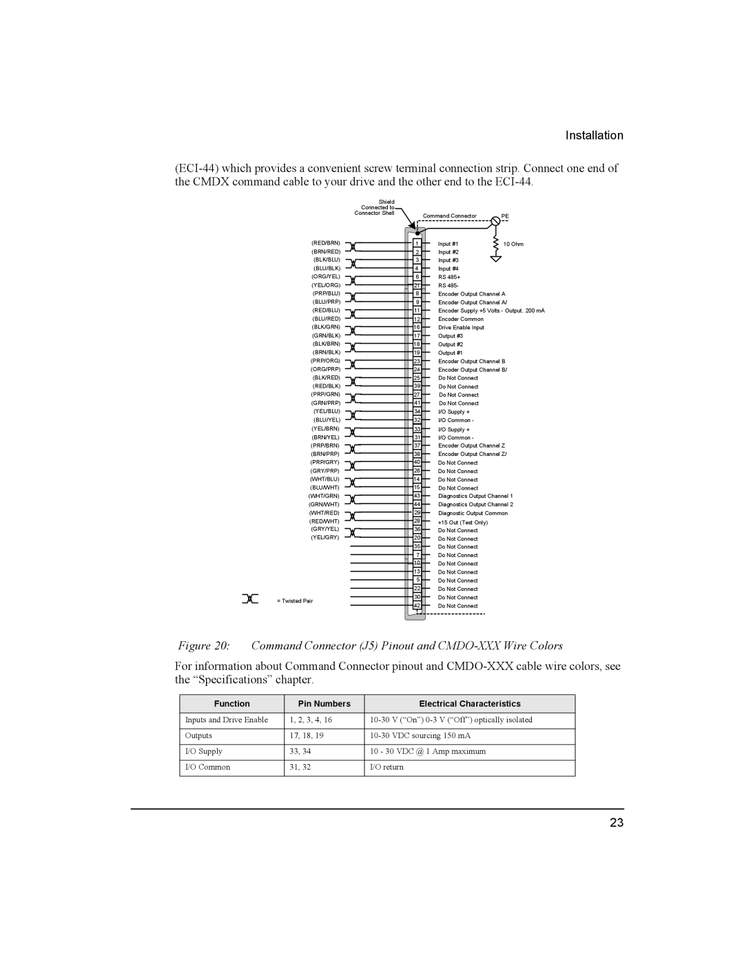
Command Connector Wiring
Function Pin Numbers Electrical Characteristics
Command Connector J5 Pinout and CMDO-XXX Wire Colors
Command Cables
Analog Command, Differential Wiring Diagram
Analog Command Wiring
Command Connector Encoder Output Wiring
Encoder Output Signal Wiring
Pulse Mode, Differential Output to Differential Input
Pulse Mode Wiring, Differential Inputs
Pulse Mode Wiring, Single Ended Inputs
Master/Slave Encoder Connections
Serial Communications
Multi-Drop Communications
Serial Communications Specifications
Modbus Communications
Multi-Drop Wiring Pinout
Display Indication Status Description
Diagnostic Display
Display Fault Action to Reset Bridge Disabled
Fault Codes
Diagnostics and Troubleshooting
Fault Descriptions
High DC Bus Threshold Low DC Bus Treshold
Power Module
Encoder State
Output Source Offset Scale
Diagnostic Analog Output Test Points
Diagnostic Cable Dgne Diagram
Drive Faults
Viewing Active Drive Faults
Resetting Faults
Rebooting the Drive
Watch Window
Watch Window
Group
View Motor Parameters
Options and Accessories
Dimensions of ECI-44
ECI-44 External Connector Interface
STI EIO
STI-EIO Interface
ECI-44 Signal Connections
Drive Specifications
Fault Detection Capability
Encoder Output Signal
Shunt Resistor Capacity
Regeneration Capacity
Drive and Motor Combination Specifications
Motor Weights
Motor Brake Specifications
Motor Max Radial Load lb Max. Axial Load lb
IP Ratings
Axial/Radial Loading
Power Dissipation
Encoder Specifications
Power Dissipation Calculation
Motor Density Output Type Output Signals Power Supply
Motor Mounting Plate Size
Speed Torque Curves
Epsilon Speed Torque Curves, sheet 1
Epsilon Speed Torque Curves, sheet 2
Following table applies to A* and B* as shown in Figure
Epsilon Drive Dimensions Eb 202, Eb-203, Eb-205
MGE-205 and 208 Motors
MG Motor Dimensions
MGE-205 and 208 Mounting Dimensions inches mm
MGE-316 and 340 Motors
MGE-316, MGM-316, and MGM-340 Mounting Dimensions Inches mm
MGE-316, MGM-316, and MGM-340 Mounting Dimensions
MGE-455, 490 and 4120 Motors
MGE-455, 490 and 4120 Mounting Dimensions inches mm
MGM-455, 490 and 4120 Motors
MGE-455, 490 and 4120 Mounting Dimensions mm inches
NTE-207 Motors English Face Nema 23 with 3/8 inch shaft
NT Motor Dimensions
NTM-207 Motors Metric Face
NTE-212 Motors English Face Nema 23 with 3/8 inch shaft
NTM-212 Motors Metric Face
Drive Signal
Cable Diagrams
CMDX-XXX Cable
CMDO-XXX Cable
CDRO-XXX Cable
AX-CEN-XXX Cable
TIA-XXX Cable
EIO-XXX Cable
DDS-XXX Cable TERM-H Head Terminator
CMDS-XXX Cable CMMS-XXX Cable
TERM-T Tail Terminator
CFCS-XXX Cable
CFCO-XXX Cable
CFOS-XXX Cable
Vendor Contact Information
Index
STI-EIO
Index
Epsilon Eb Digital Servo Drive Installation Manual