MODEL | SECTION 5.0 |
| PROGRAMMING THE ANALYZER |
5.7.2 Procedure – Configuring Security Settings
Program
Alarms
Measurement
Temperature
Security
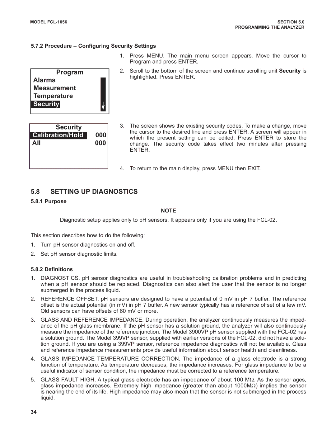
1.Press MENU. The main menu screen appears. Move the cursor to Program and press ENTER.
2.Scroll to the bottom of the screen and continue scrolling unit Security is highlighted. Press ENTER.
Security
Calibration/HoldCalibration/Hold 000
All000
3.The screen shows the existing security codes. To make a change, move the cursor to the desired line and press ENTER. A screen will appear in which the present setting can be edited. Press ENTER to store the change. The security code takes effect two minutes after pressing
ENTER.
4.To return to the main display, press MENU then EXIT.
5.8SETTING UP DIAGNOSTICS
5.8.1 Purpose
NOTE
Diagnostic setup applies only to pH sensors. It appears only if you are using the
This section describes how to do the following:
1.Turn pH sensor diagnostics on and off.
2.Set pH sensor diagnostic limits.
5.8.2 Definitions
1.DIAGNOSTICS. pH sensor diagnostics are useful in troubleshooting calibration problems and in predicting when a pH sensor should be replaced. Diagnostics can also alert the user that the sensor is no longer submerged in the process liquid.
2.REFERENCE OFFSET. pH sensors are designed to have a potential of 0 mV in pH 7 buffer. The reference offset is the actual potential (in mV) in pH 7 buffer. A new sensor typically has a reference offset of a few mV. Old sensors can have offsets of 60 mV or more.
3.GLASS AND REFERENCE IMPEDANCE. During operation, the analyzer continuously measures the imped- ance of the pH glass membrane. If the pH sensor has a solution ground, the analyzer will also continuously measure the impedance of the reference junction. The Model 3900VP pH sensor supplied with the
4.GLASS IMPEDANCE TEMPERATURE CORRECTION. The impedance of a glass electrode is a strong function of temperature. As temperature decreases, the impedance increases. For glass impedance to be a useful indicator of sensor condition, the impedance must be corrected to a reference temperature.
5.GLASS FAULT HIGH. A typical glass electrode has an impedance of about 100 MΩ. As the sensor ages, glass impedance increases. Extremely high impedance (greater than about 1000MΩ) implies the sensor is nearing the end of its life. High impedance may also mean that the sensor is not submerged in the process liquid.
34
