FCL with 1056 Analyzer
Essential Instructions
English
Free Chlorine
Ppm mg/L
ORP
S1 Manual pH Temp Units
S1 Free Cl PH Correction Manual
Live/Continous
Sensor 2 pH
Menu Tree
Calibrate Sensor 1 Free chlorine
Alarms
Temperature
Diagnostic Setup
Reset Analyzer
About This Document
Rev. Level Date
Table of Contents
FCL-1056
Table of Contents CONT’D
List of Tables
List of Tables CONT’D
Iii
Applications
Section Description and Specifications
Features
Specifications Analyzer
Specifications General
Specifications Sensor
Accessories
Ordering Information
Component Parts
PH Correction required selection
This page left blank intentionally
Section Installation
Unpacking and Inspection
FCL-01 free chlorine without continuous pH correction
FCL-02 free chlorine with continuous pH correction
Installation
Installing the Sensors
General Information
Mounting, Inlet, and Drain Connections
Model FCL-01
This page left blank intentionally
Section Wiring
POWER, ALARM, and Output Wiring
Power
Analog output wiring
Sensor Wiring
Alarm relay connections
Wiring Diagram for Free Chlorine Sensor
Model FCL-1056 Section Wiring
Section Display and Operation
Display
Keypad
Programming the ANALYZER-TUTORIAL
Calibrate
Outputs
Range
Output Range O1 S1 4mA 0.000 ppm
O1 S1 20mA 08.50 ppm
O2 S1 4mA 0.0C O2 S1 20mA 100.0C
Security
Using Hold
Hold
Configuring the Main Display
Main Format
Language English Contrast
Format, Language, Warning, and Contrast
General
Default Settings
Section Programming the Analyzer
Alarms
Sensor assignment
Choices Default
CONFIGURING, RANGING, and Simulating Outputs
Definitions
Assign
Configure
ProgramOutput
Configure Simulate Output Configure
Procedure Ranging Outputs
Output Output Range
O1 S1 20mA 10.00 ppm O2 S1 4mA 0.0C O2 S1 20mA 100.0C
Configure Simulate
Configuring Alarms and Assigning Setpoints
RangeSimulate
Output
Section Programming the Analyzer
Alarm
Alarms
Configure/Setpoint
Alarms Configure/Setpoint
Alarm Simulate Alarm
Simulate
Don’t Simulate
Procedure Synchronizing Timers
Alarms Configure/Setpoint Simulate
Synch Timers Yes
Definitions pH/ORP
Configuring the Measurement
Definitions Chlorine
Measurement
Sensor1Sensor
Configuring Temperature Related Settings
Definitions pH
Program Outputs Alarms Measurement
Temperature
Configuring Security Settings
S1 Temp Comp Auto S2 Temp Comp
Program Alarms Measurement Temperature
Setting UP Diagnostics
Security
Security
Program Measurement Temperature Security
Diagnostic Setup
GI Fault High 1500MΩ
Procedure Setting Up Diagnostics
Resetting the Analyzer
Program Temperature Security Diagnostics
Reset Analyzer
Reset Analyzer
Introduction
Calibrating Temperature
Section Calibration
Procedure
Calibrate SensorSensor11 Output
S1 Calibration
S1 Calibration + 25.0C
Procedure-Zeroing the Sensor
Calibration Free Chlorine
Calibrate SensorSensor11 Output S1 Calibration
Choose Free Chlorine
Temperature S1 Calibration ZeroZeroCalCal Process Cal
Calibrate?
Sensor
Sensor Output
Calibration pH
Calibration Slope and Offset
ZeroBufferCalCal
Auto
Stable Time
07.01 pH
10.01 pH
Manual
Buffer
Manual Buffer 1 0 7.00 pH S2 pH Manual Cal Buffer
Redox Temperature S2 pH Cal Buffer Cal
StandardizeStandardize
Slope 56.19 mV/pH Offset
S1 Enter Value 00 pH
Procedure-Entering a Known Slope and Offset
MA Output Cal Meter 000 mA Trim Complete
Calibration Analog Outputs
Output
This page left blank intentionally
Section Digital Communications
Model FCL-1056 Section
Section Maintenance
Analyzer
Cleaning the membrane
Replacing the electrolyte solution and membrane
Chlorine Sensor
General
PH Sensor
Cleaning the Sensor
Other Maintenance
Cleaning the flow controller
Constant Head Flow Controller
Weight
Weight
Section Troubleshooting
Using the Diagnostic Feature
Faults
Overview
Hardware Error
Troubleshooting When a Fault Message is Showing
Fault message Explanation Section
Sensor CPU Error
Sensor ADC Error
Sensor Incompatible
Sensor RTD Open
Sensor RTD Out of Range
Glass Z Too High
Reference Impedance Too High
Broken Glass
Troubleshooting When a Warning Message is Showing
Troubleshooting When no Error Message is Showing Chlorine
Readings drift
Sensor can be calibrated, but the current is too low
Process readings are erratic
Sensor does not respond to changes in chlorine level
Chlorine readings are too low
Troubleshooting When no Error Message is Showing pH
Calibration Error During Two-Point Calibration
Calibration Error during Standardization
Sensor Does Not Respond to Known pH Changes
PH Readings Are Moderately Noisy and Tend to Wander
Troubleshooting When no Error Message is Showing General
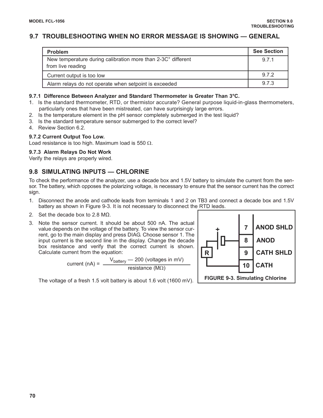
Simulating Inputs Chlorine
Anod
Cath
Simulating Inputs pH
Simulating pH input
Simulating Inputs Temperature
Simulating temperature
Page
Americas Headquarters
ASIA-PACIFIC
Europe
Germany
Warranty
Specifications subject to change without notice

