EPSON
Table
Problem |
| Cause |
| Checkpoint |
| Solution |
Chapter 3 Troubleshooting
Table
Problem |
| Cause |
| Checkpoint |
| Solution |
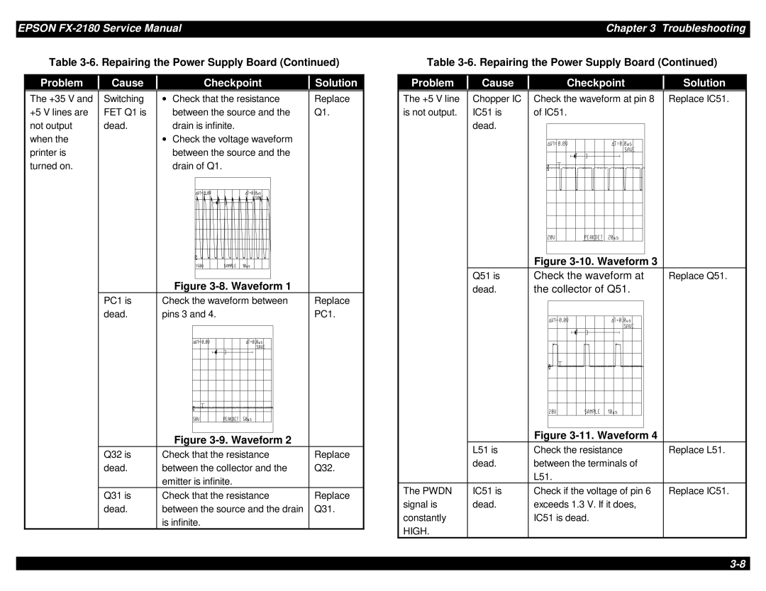
The +35 V and +5 V lines are not output when the printer is turned on.
Switching | ∙ | Check that the resistance | Replace | |||||||||||
FET Q1 is |
| between the source and the | Q1. | |||||||||||
dead. |
| drain is infinite. |
| |||||||||||
| ∙ | Check the voltage waveform |
| |||||||||||
|
| between the source and the |
| |||||||||||
|
| drain of Q1. |
| |||||||||||
|
|
|
|
|
|
|
|
|
|
|
|
|
|
|
|
|
|
|
|
|
|
|
|
|
|
|
|
|
|
|
|
|
|
|
|
|
|
|
|
|
|
|
|
|
|
|
|
|
|
|
|
|
|
|
|
|
|
|
|
|
|
|
|
|
|
|
|
|
|
|
|
|
|
|
|
|
|
|
|
|
|
|
|
|
|
|
|
|
|
|
|
|
|
|
|
|
|
|
|
|
|
|
|
|
|
|
|
|
|
|
|
|
|
|
|
|
|
|
|
|
|
|
|
|
|
|
|
|
|
|
|
|
|
|
|
|
|
|
|
|
|
|
|
|
|
|
|
|
|
|
|
|
|
|
|
|
|
|
|
|
|
|
|
|
| Figure |
| |||||||||||
PC1 is | Check the waveform between | Replace | |||||||||||
dead. | pins 3 and 4. | PC1. | |||||||||||
|
|
|
|
|
|
|
|
|
|
|
|
|
|
|
|
|
|
|
|
|
|
|
|
|
|
|
|
|
|
|
|
|
|
|
|
|
|
|
|
|
|
|
|
|
|
|
|
|
|
|
|
|
|
|
|
|
|
|
|
|
|
|
|
|
|
|
|
|
|
|
|
|
|
|
|
|
|
|
|
|
|
|
|
|
|
|
|
|
|
|
|
|
|
|
|
|
|
|
|
|
|
|
|
|
|
|
|
|
|
|
|
|
|
|
|
|
|
|
|
|
|
|
|
|
|
|
|
|
|
|
|
|
|
|
|
|
|
|
|
|
|
|
|
|
|
|
|
|
|
|
|
|
|
| Figure |
|
Q32 is | Check that the resistance | Replace |
dead. | between the collector and the | Q32. |
| emitter is infinite. |
|
Q31 is | Check that the resistance | Replace |
dead. | between the source and the drain | Q31. |
| is infinite. |
|
The +5 V line | Chopper IC | Check the waveform at pin 8 Replace IC51. | ||
is not output. | IC51 is | of IC51. | ||
| dead. |
|
|
|
|
|
|
| |
Figure |
Q51 is | Check the waveform at | Replace Q51. |
dead. | the collector of Q51. |
|
Figure |
| L51 is | Check the resistance | Replace L51. |
| dead. | between the terminals of |
|
|
| L51. |
|
The PWDN | IC51 is | Check if the voltage of pin 6 | Replace IC51. |
signal is | dead. | exceeds 1.3 V. If it does, |
|
constantly |
| IC51 is dead. |
|
HIGH. |
|
|
|