EPSON | Appendix |
|
|
A.1 Connector Summary
Table
Board |
| Connector |
| Function |
| Pins |
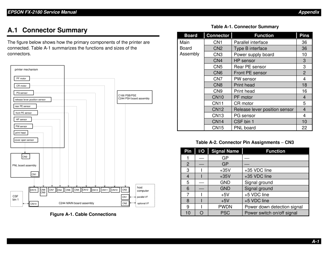
The figure below shows how the primary components of the printer are connected. Table A-1 summarizes the functions and sizes of the
Main |
| CN1 | Parallel interface | 36 |
|
Board | CN2 | Type B interface | 36 |
| |
connectors.
printer mechanism
PF motor
CR motor
PG sensor
release lever position sensor
rear PE sensor
front PE sensor
HP sensor
PW sensor
print head
cover open sensor
CN2
PNL board assembly
CN1
C166 PSB/PSE
C244 PSH board assembly
Assembly | CN3 | Power supply board | 10 |
|
| CN4 | HP sensor | 3 |
|
| CN5 | Rear PE sensor | 3 |
|
| CN6 | Front PE sensor | 2 |
|
| CN7 | PW sensor | 4 |
|
| CN8 | Print head | 18 |
|
| CN9 | Print head | 16 |
|
| CN10 | PF motor | 4 |
|
| CN11 | CR motor | 5 |
|
| CN12 | Release lever position sensor | 4 |
|
| CN13 | PG sensor | 4 |
|
| CN14 | CSF bin 1 | 10 |
|
| CN15 | PNL board | 22 |
|
|
|
| Table |
| ||||
|
|
|
|
|
|
|
|
|
| Pin |
| I/O |
| Signal Name |
| Function |
|
|
|
|
|
| ||||
|
|
|
|
|
|
|
|
|
| 1 |
| ⎯ |
| GP |
| ⎯ |
|
| 2 |
| ⎯ |
| GP |
| ⎯ |
|
| 3 |
| I |
| +35V |
| +35 VDC line |
|
| 4 |
| I |
| +35V |
| +35 VDC line |
|
| 5 |
| ⎯ |
| GND |
| Signal ground |
|
CN15 | CN8 | CN7 | CN4 | CN6 | CN5 | CN12 | CN13 | CN11 | CN10 | CN3 | host |
computer | |||||||||||
| CN9 |
|
|
|
|
|
|
|
|
|
|
CSF | CN1 | parallel I/F |
bin 1 |
|
|
CN14 | C244 MAIN board assembly | CN2 | optional I/F |
Figure A-1. Cable Connections
| 6 | ⎯ | GND | Signal ground |
|
| 7 | I | +5V | +5 VDC line |
|
| 8 | I | +5V | +5 VDC line |
|
| 9 | I | PWDN | Power down detection signal |
|
| 10 | O | PSC | Power switch on/off signal |
|