EPSON | Chapter 4 Disassembly and Assembly |
4.2.11.11 Removing the Front PE Sensor Assembly | 4.2.11.12 Removing the Main Board Assembly |
1.Remove the printer cover, front and rear edge guide assemblies, front cover, paper eject assembly, and front and rear tractor units. (See section 4.2.1.)
2.Remove the panel board assembly. (See section 4.2.2.)
3.Remove the upper housing assembly. (See section 4.2.7.)
4.Remove the printer mechanism. (See section 4.2.11.)
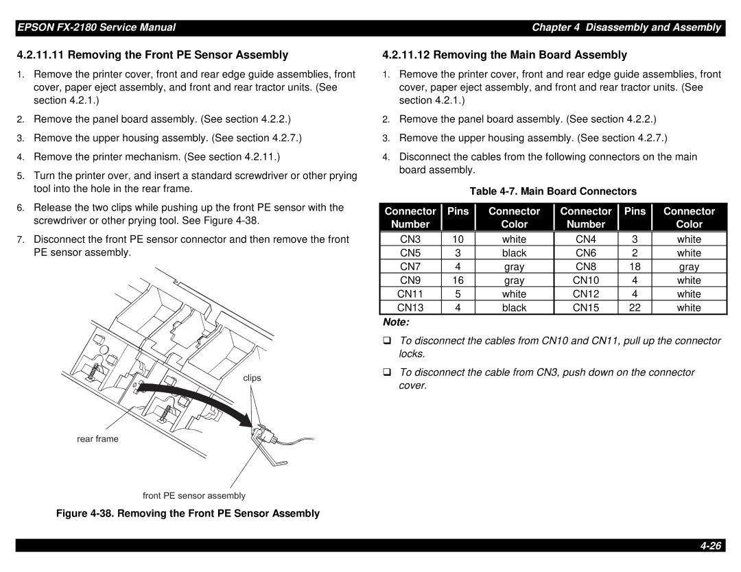
5.Turn the printer over, and insert a standard screwdriver or other prying tool into the hole in the rear frame.
1.Remove the printer cover, front and rear edge guide assemblies, front cover, paper eject assembly, and front and rear tractor units. (See section 4.2.1.)
2.Remove the panel board assembly. (See section 4.2.2.)
3.Remove the upper housing assembly. (See section 4.2.7.)
4.Disconnect the cables from the following connectors on the main board assembly.
Table
6. | Release the two clips while pushing up the front PE sensor with the | Connector |
| Pins |
| Connector |
| Connector |
| Pins |
| Connector |
|
| screwdriver or other prying tool. See Figure |
|
|
|
|
|
| ||||||
| Number |
|
|
| Color |
| Number |
|
|
| Color |
| |
|
|
|
|
|
|
|
|
|
|
7.Disconnect the front PE sensor connector and then remove the front PE sensor assembly.
![]() c l i p s
c l i p s
CN3 | 10 | white | CN4 | 3 | white |
CN5 | 3 | black | CN6 | 2 | white |
CN7 | 4 | gray | CN8 | 18 | gray |
CN9 | 16 | gray | CN10 | 4 | white |
CN11 | 5 | white | CN12 | 4 | white |
CN13 | 4 | black | CN15 | 22 | white |
Note:
To disconnect the cables from CN10 and CN11, pull up the connector
Ylocks.
To disconnect the cable from CN3, push down on the connector cover.
r e a r f r a m e |
|
f r o n t | P E s e n s o r a s s e m b ly |