EPSON
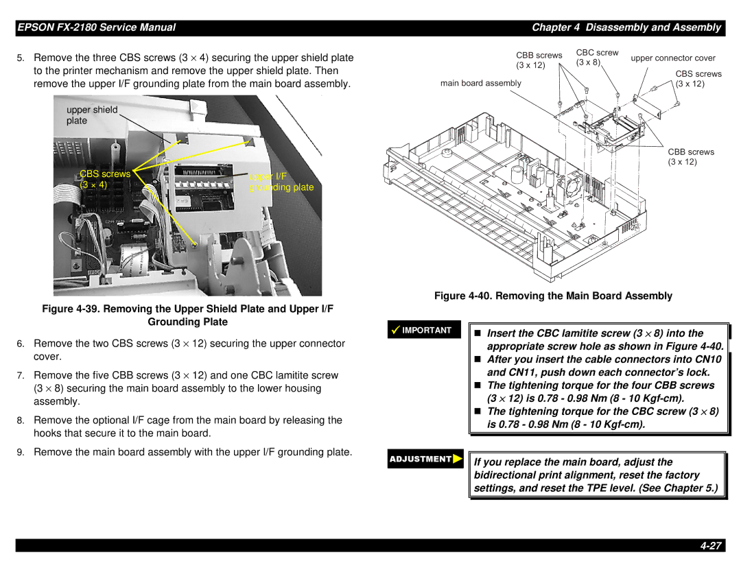
5.Remove the three CBS screws (3 × 4) securing the upper shield plate to the printer mechanism and remove the upper shield plate. Then remove the upper I/F grounding plate from the main board assembly.
upper shield plate
CBS screws | upper I/F |
(3 × 4) | grounding plate |
Figure 4-39. Removing the Upper Shield Plate and Upper I/F
Chapter 4 Disassembly and Assembly
C B B | C B C | s c r e w | |
s c r e w s | |||
| ( 3 | x | u p p e r c o n |
( 3 x | 8 ) | ||
1 2 ) |
| C B S s | |
|
|
| |
m a in b o a r d a s s e m b ly( 3 x 1
C B B | s c |
( 3 x | 1 |
Figure 4-40. Removing the Main Board Assembly
Grounding Plate
6.Remove the two CBS screws (3 × 12) securing the upper connector cover.
7.Remove the five CBB screws (3 × 12) and one CBC lamitite screw (3 × 8) securing the main board assembly to the lower housing assembly.
8.Remove the optional I/F cage from the main board by releasing the hooks that secure it to the main board.
9.Remove the main board assembly with the upper I/F grounding plate.
IMPORTANT
Insert the CBC lamitite screw (3 × 8) into the appropriate screw hole as shown in Figure
T(3 × 12) is 0.78 - 0.98 Nm (8 - 10
The tightening torque for the CBC screw (3 × 8) is 0.78 - 0.98 Nm (8 - 10
If you replace the main board, adjust the bidirectional print alignment, reset the factory settings, and reset the TPE level. (See Chapter 5.)